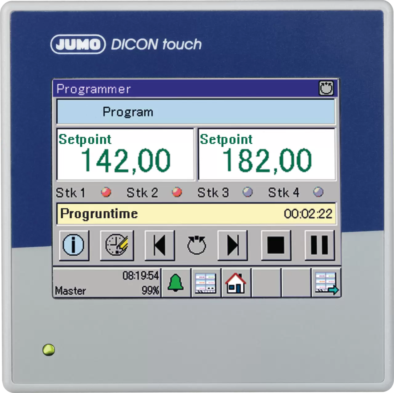
Two/four channel process and program control
Find out more about the benefits and related technical specifications of the JUMO DICON touch
Productinfos
Find out more about the benefits and related technical specifications of the JUMO DICON touch
ProductinfosIf the setup connector is connected to the controller, the relay module will not be controlled by the interface and the relay contacts will remain in the quiet position.
Subsequent release of the math and logic option can be achieved using the installation program on the Dicon 40x/50x and interface connection to the controller.
The controller does not need to be fully connected to release this option; Only the controller supply voltage must be connected.
Interface connection can be easily implemented with interface JUMO USB-TTL-Interface or with interface JUMO RS232-TTL-Interface via the standard controller software interface.
As an alternative to connecting interface JUMO, the additional interface RS485/RS422 can be used to establish the connection.
Access the menu for issuing mathematical and logical options through the menu "Extras" - "Issuing additional codes". Before getting to this menu, please open the configuration file (for example, through the menu "File" - "New").
When "numerical code number" is displayed, the code number is displayed - to issue the above options JUMO this code number must be provided.
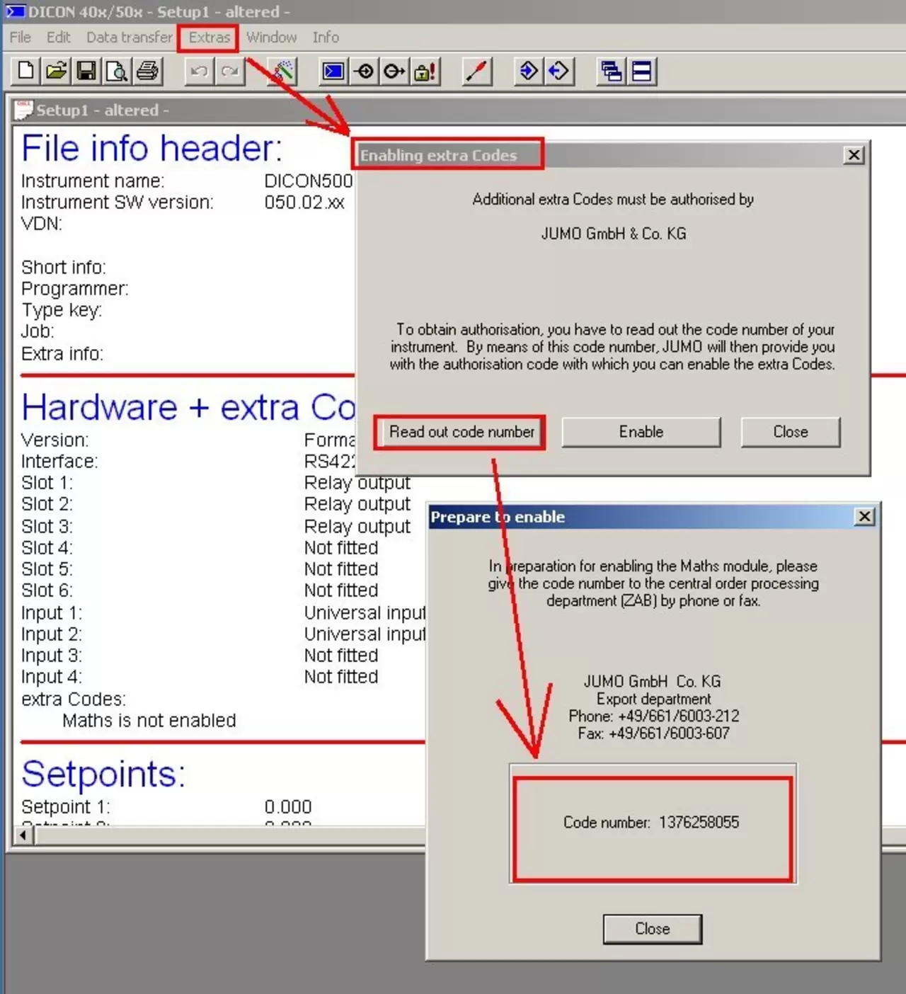
Generated code number incl. possible sign, can be provided by email, fax or telephone. Upon receiving this number, JUMO generates a release code and notifies you of it.
Please enter this release number you receive from JUMO as follows:
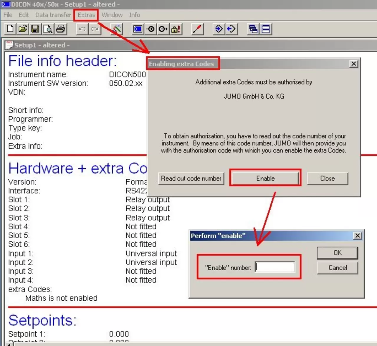
The release of the math/logic option is completed when the release code is entered and confirmed.
In order to edit the corresponding mathematical or logical formula in the setup program, you need to either re-run the automatic identification or manually configure the released option under "Software".
Available measuring range options depend on hardware configuration.
This can be changed by changing the position of the two jumpers.
For ranges -10/0/2 - 10 The jumpers on the CPU board (inputs 1 and 2) or on the input board (inputs 3 and 4) must be set as follows:
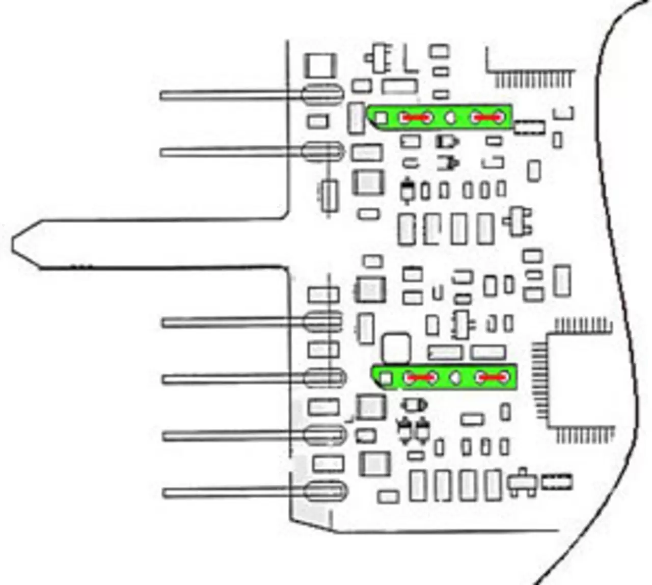
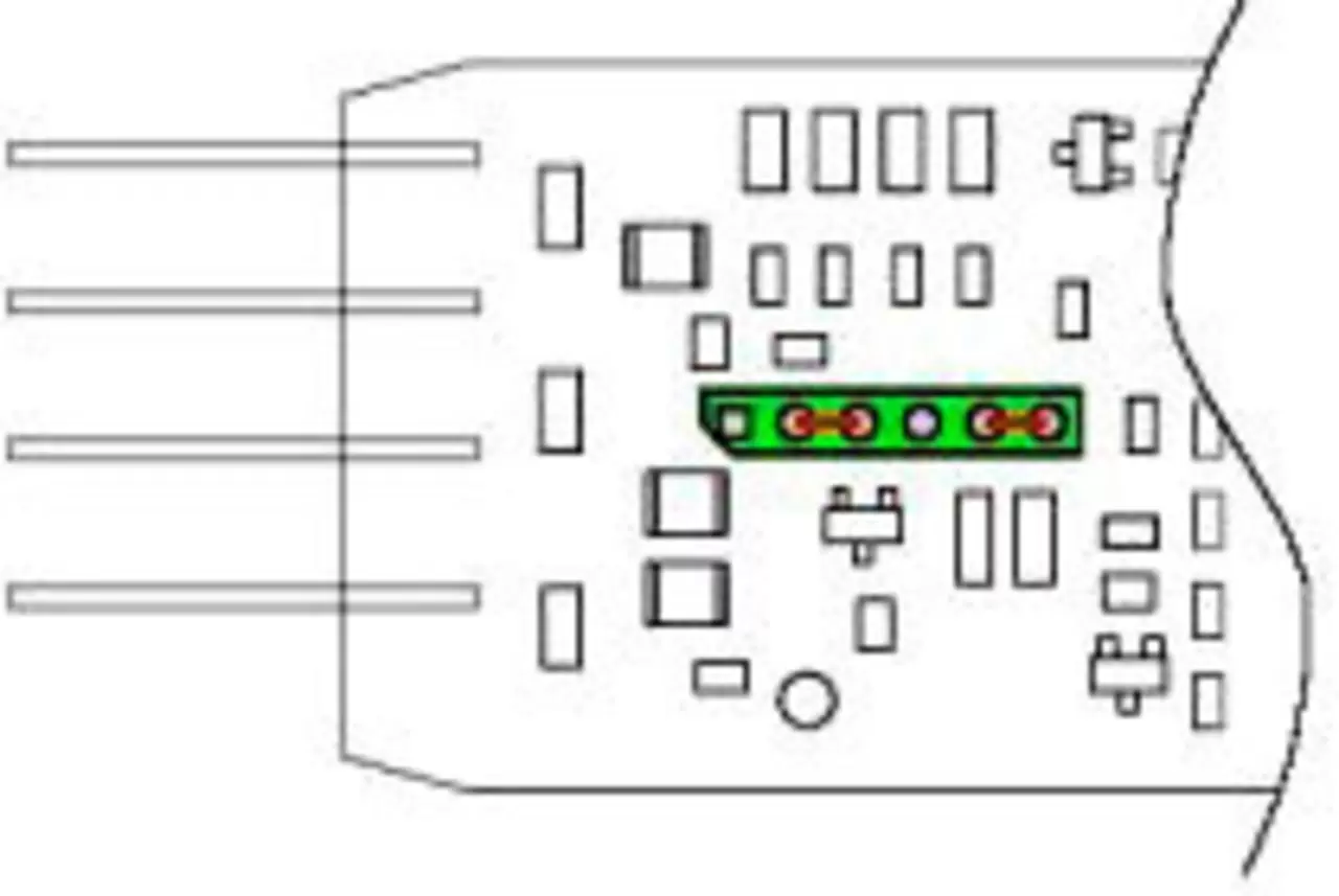
Acceptance of the address only takes effect when the delivery is switched off and on again (DICON).
JUMO DICON 400/500 or 401/501 provides the possibility of programming up to 8 such limit value comparators.
To make best use of the limit comparator, it must be programmed for the required switching response.
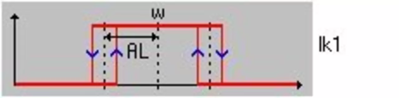
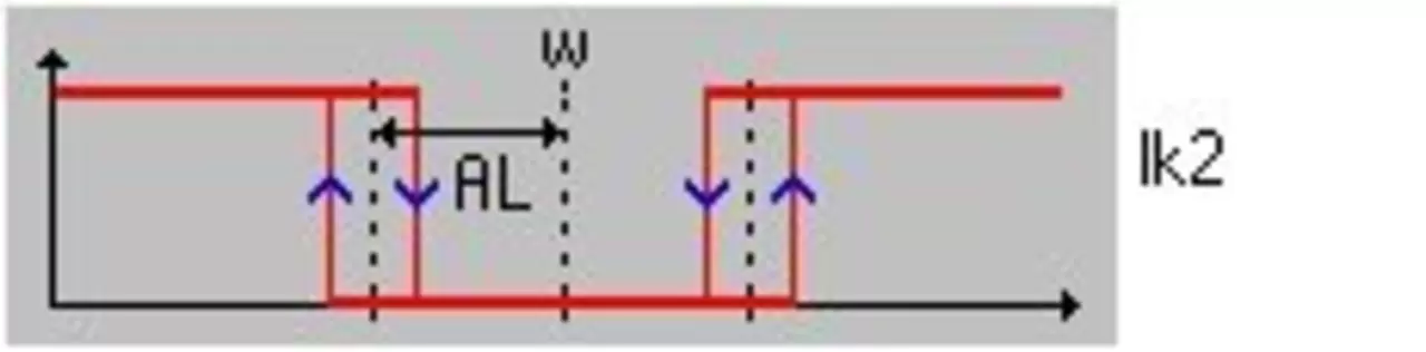
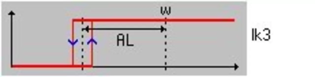
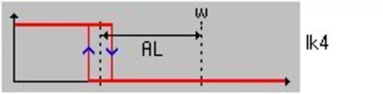
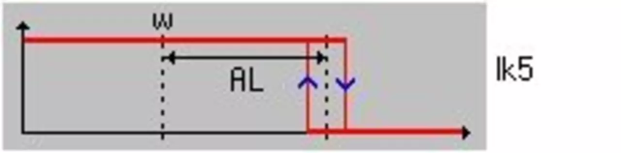
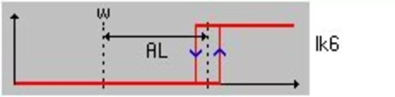
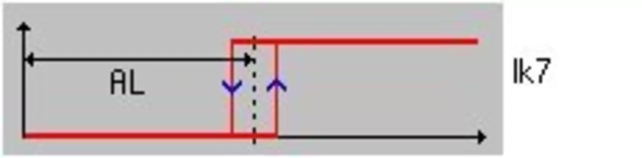
The switching response is determined by the limit comparator functions (lk 1 - lk 8).
lk 1 - lk 6 are set point based functions and lk 7 - lk 8 are fixed limit based functions.
For lk 1 - lk 6, AL (alarm level) is the difference between the set point W1 and the on or off point.
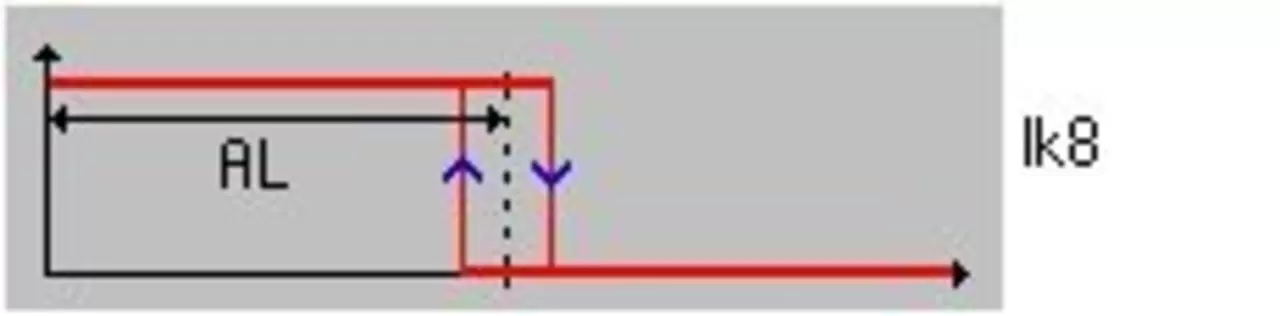
For lk 7 - lk 8 the value AL is the absolute limit at which the contact turns on or off.
Example:
Function lk 8 > limit value 70 °C, the assigned output remains on unless the process value rises above 70 °C, after which it turns off.
If the process value drops below 70 °C, the output is switched on again.
The switch return point can also be controlled by the shift differential.
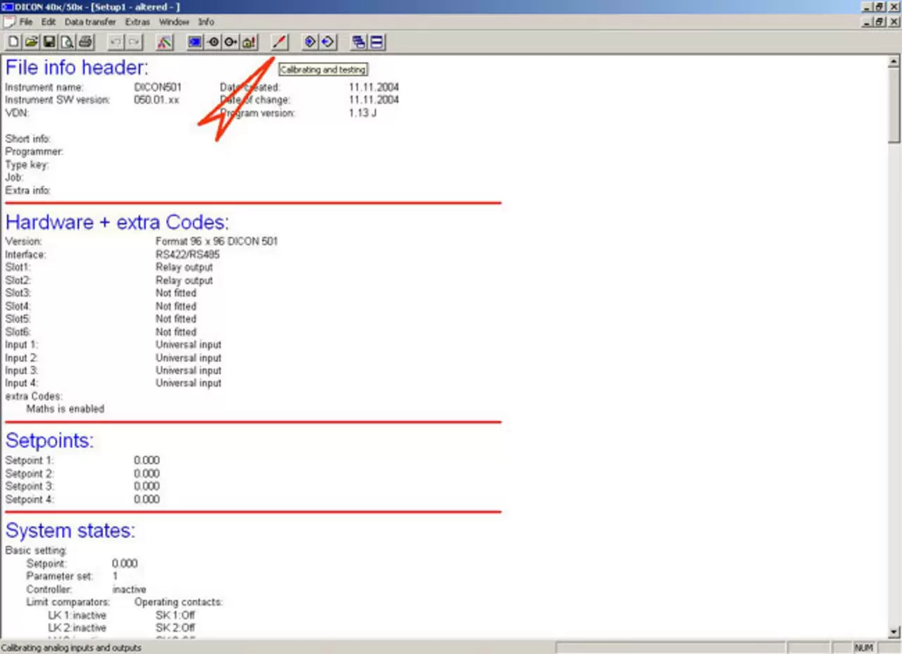
At this level you can test the display, keys, output switching, and so on.
SERVICE
The matrix display alternates between “Code-NR” and “0000”. Use the [Enter] key to move one digit to the left, use the arrow keys to set "7", and press the [Enter] key 3 times.
ANZEIG
All displays will be illuminated.
Keys
The keys pressed will be indicated in plain text on the matrix display (display 3).
LOGICAL B
The matrix display indicates "00000000". Setting the logic inputs to "0" (for example, closing a contact) changes each of the zeros to "1", for example "11111111" (depending on the version installed).
RELAYS
Outputs 1 - 6 [Enter] -> To switch outputs (relays, solid state relays, logic): outputs can be switched using the arrow keys. When the keys are released the relays drop out again.
This test function has no effect on analog outputs or logic inputs.
INTPT100
The matrix display shows alternately "Temp" and the cold joint temperature currently measured (for thermocouples, in the rear panel).
SCHNITTS (interface)
The device shows a count of the number of commands received in the upper display (display 1).
In the middle display (display 2) the device shows a count of the number of commands sent.
Note:
On devices that communicate only through the setup program, both accounts must be identical. The [Enter] key can be used to reset the count to "0".
The corresponding output must be configured as "2 REGAUS" or "Controller output 2".
It is also necessary to check that the controller parameter Y2 is set to -100.
The controller output types must be determined before self-optimization begins.
When the device is used as a program controller, the [Exit/manual] key must be set to manual mode. Then use the arrow keys to set a set point close to reality for the process and confirm with the [Enter] key.
Now press the following keys simultaneously: [PGM] + [Automatic].
Self-optimization will stop on its own.
It can also be canceled using the key combination [PGM] + [Automatic].
To enter the cost, first enter a whole number.
If the decimal position of the point is needed, it can be moved up or down (i.e. left or right) using [ENTER+UP] or [ENTER+DOWN]. In this case, the last decimal place must be zero.
Note:
The decimal point is only present if the decimal place has been programmed into the display configuration. If this is not done, the controller will round the input up or down.
So there is a difference between display and input value.
If, for example, a given point is configured for a display with only one decimal place, then a value entered with two decimal places will be rounded up or down to give only one decimal place.
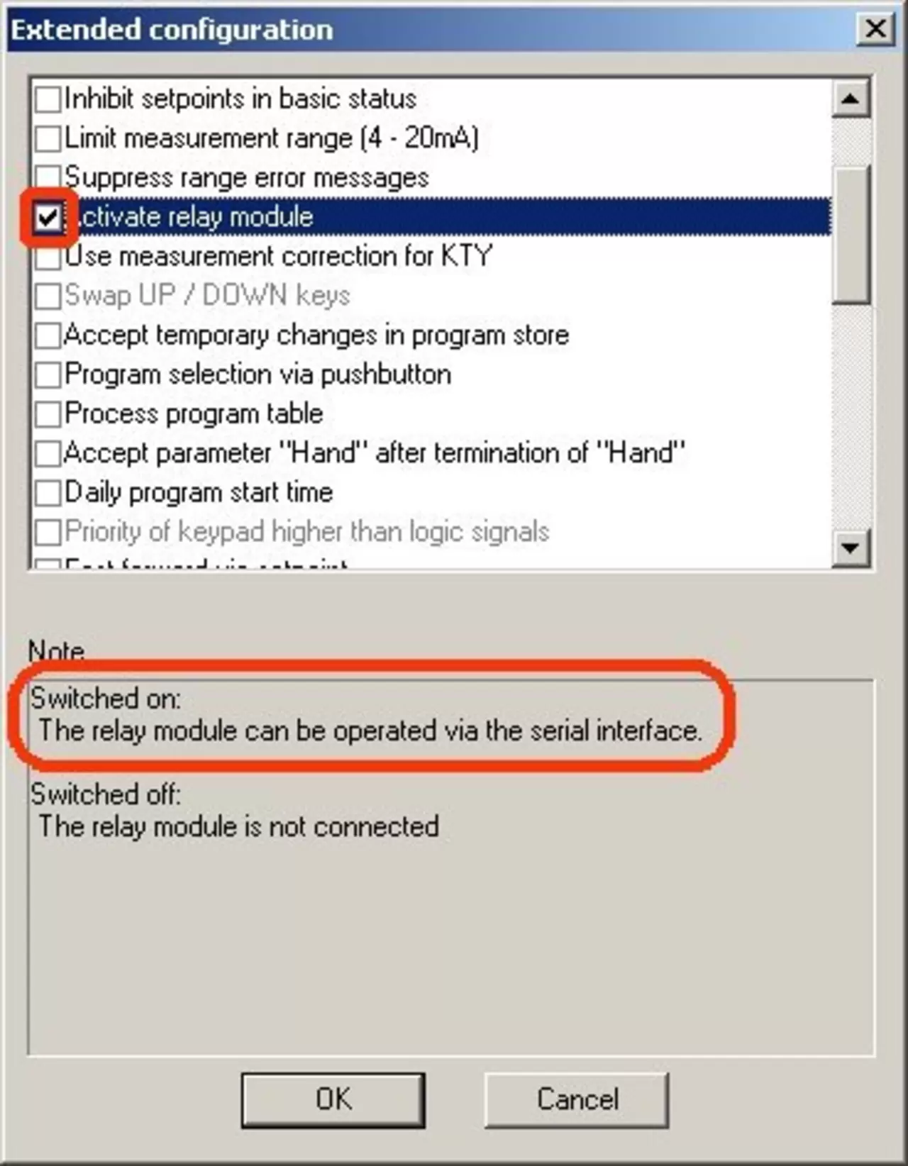
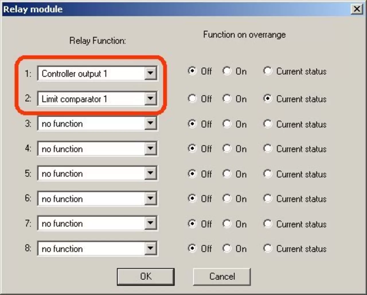
You can only use an external relay module in combination with Setting up the programThe control function for relay modules is activated by placing a tick mark for “Activate relay module” in the advanced configuration.
PT100, 3 wires
For testing, connect terminals 10 and 11 of input 1, and connect a fixed resistor or resistance dec between 9 and 10.
Thermocouple
For testing, the input terminals 10 and 11 1 are connected.
If the input is working correctly, the controller will indicate the ambient temperature.
Current/voltage input
For testing, set the input from 1 to 0-20 mA or 0-10V.
If the input is open, the display will indicate the lower zoom value (the start of the display range).
If a 20 mA or 10 V source is connected, the upper scaling value (end of the display range) will be indicated. In the standard this corresponds to 0-100 %.
Resistor/Decade Resistance Value | Indicative value |
|---|---|
18,52 Ohm | -200 °C |
100 Ohm | 0 °C |
109,73 Ohm | 25 °C |
390.481 Ohm | 850 °C |
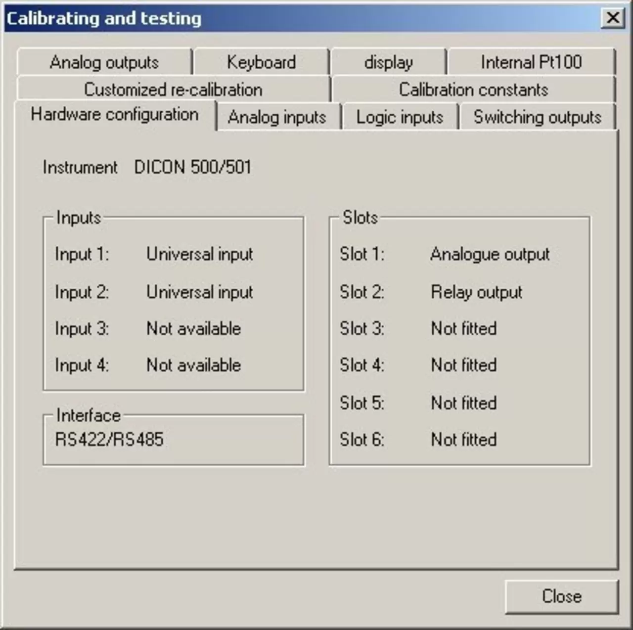
Use the maintenance mode on the device or the calibration and test function in the setup program.
In general, only 500/501 provides the possibility of upgrading to 2 inputs.
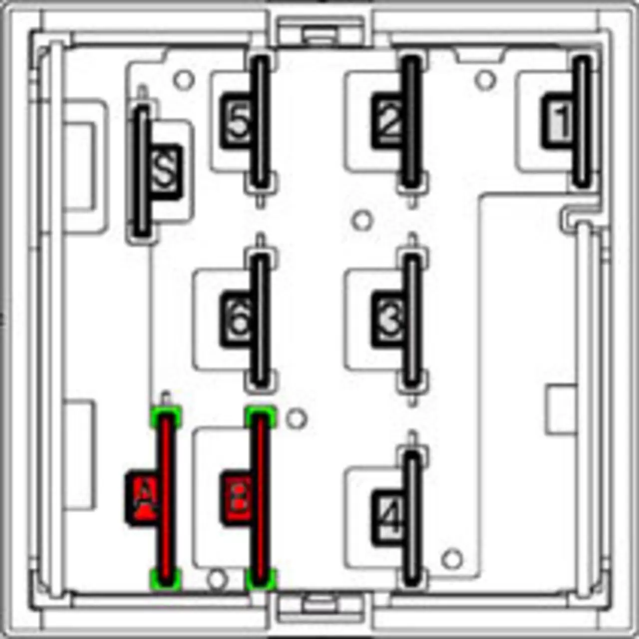
They can only be inserted into slots A and B, which are reserved for this purpose.
If the upgraded input operates in the signal range -10/0/2-10 V, then the hardware configuration needs to be checked.
You will need a converter from RS232 to Profibus DP.
Start generator JUMO GSD.
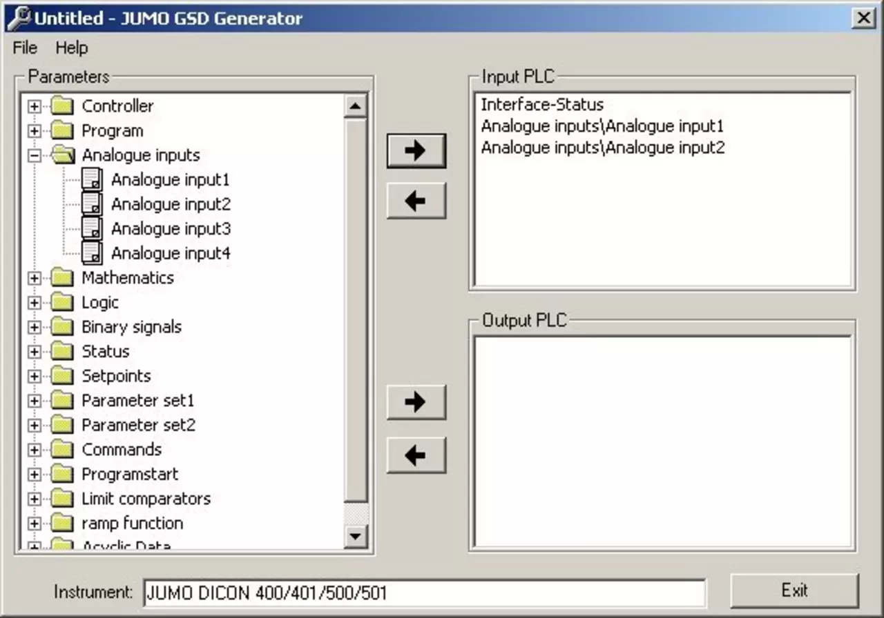
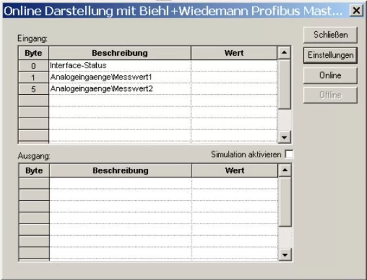
Mathematical and logical formulas are entered through the installation program on the PC.
Formulas cannot be edited via keys on the device.
The following passwords are factory defined:
Parameter level | 0001 |
Configuration level | 0002 |
calibration | 0004 |
Program editor | 1000 |
Remove programs | 1001 |
Operating mode | 0070 |
If the device is used as a process controller/fixed set point, the controller output level is set when using manual mode.
If the device is used as a program controller, a fixed point is set when using manual mode, and the controller adjusts this reference point.
If the <Exit/Hand> key is pressed while a program is running, a temporary change in the reference point can be programmed. This will only be effective for running a program currently in progress. After starting a new program, the values defined in the program editor will be applied.
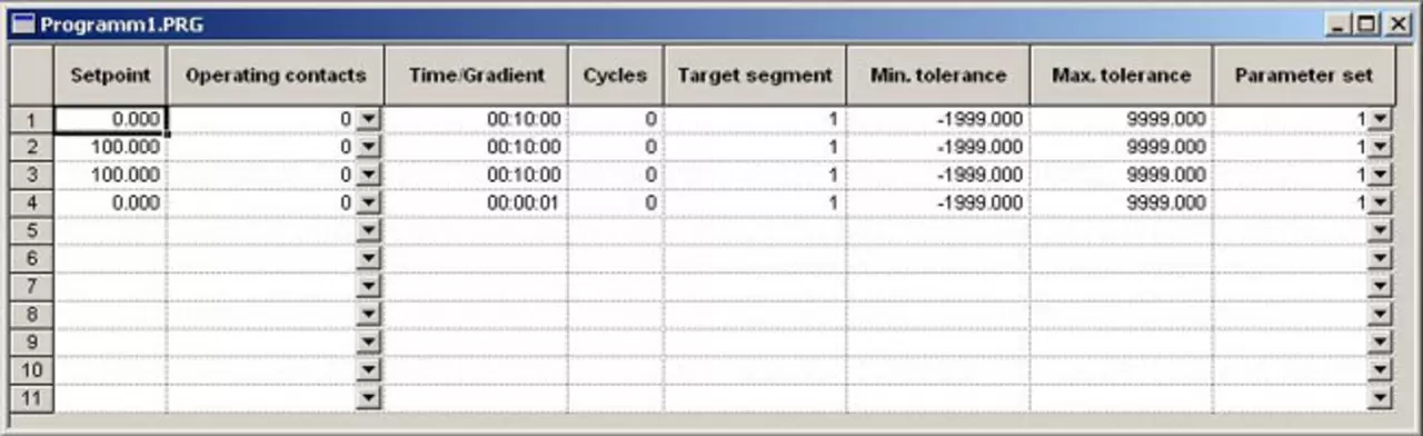
You can either enter points and times directly on the device, or use a PC program to write a program file that is transferred to the device.
This is a programming example for the following program profile:
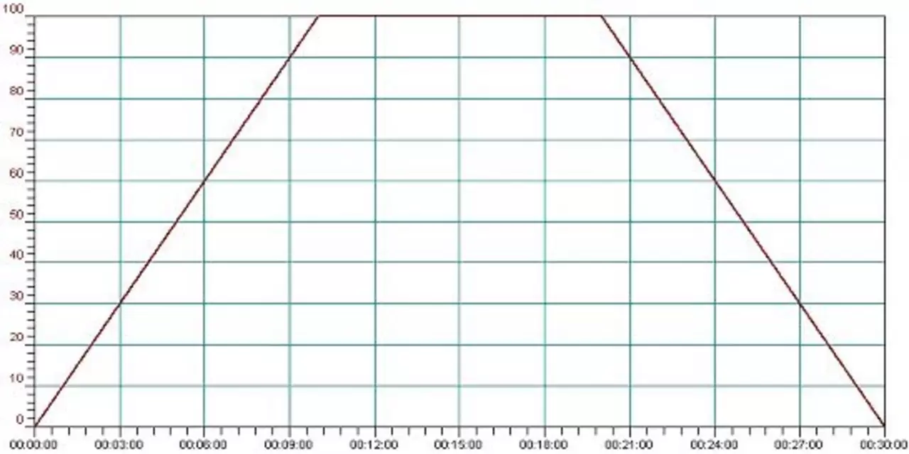
Segment number | Settings | Segment time |
|---|---|---|
01 | 0 | 00:10:00 |
02 | 100 | 00:10:00 |
03 | 100 | 00:10:00 |
04 | 0 | 00:00:01 |