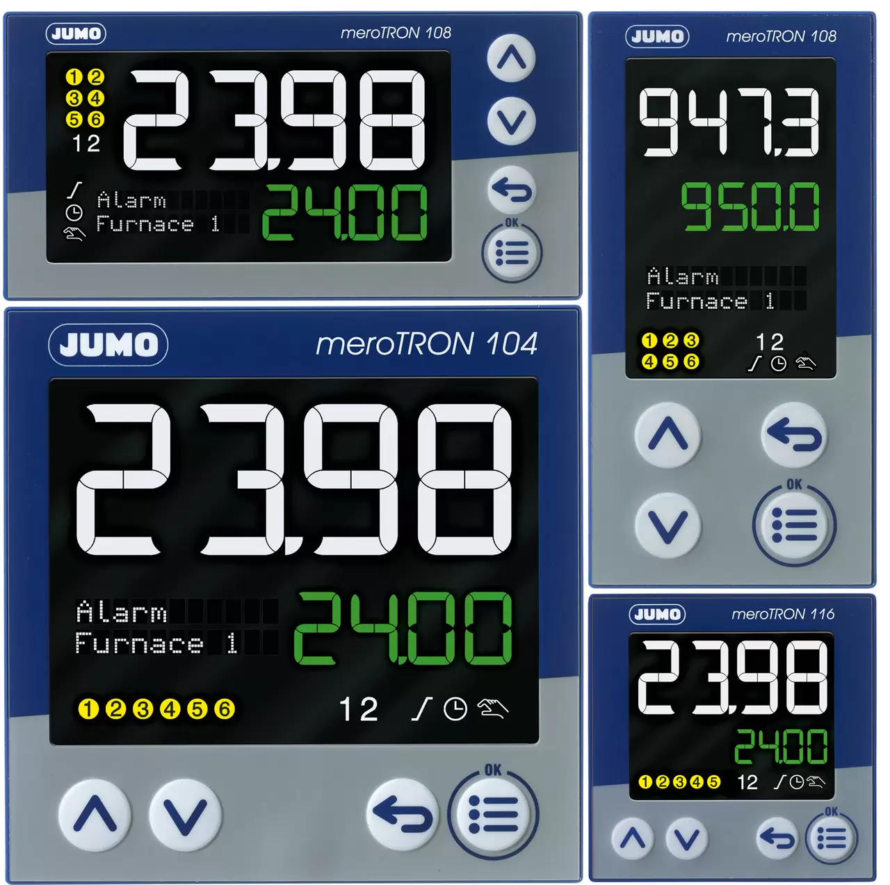
Modular single/dual channel controller with PLC function
Find out more about the benefits and related technical specifications of the JUMO meroTRON
Productinfos
Find out more about the benefits and related technical specifications of the JUMO meroTRON
ProductinfosThis signals that an excessive/disordered external set point condition has occurred.
This includes:
If "1999" flashes, it means that there is either no measurable signal (test break) or the configuration under C111 is incorrect.
1.Check the measuring signal (resistance measurement, current/voltage measurement), if necessary, determine the values using the signal source.
2.Check configuration code C111 (default setting Pt100, Chapter 7.1 Operation Instructions).
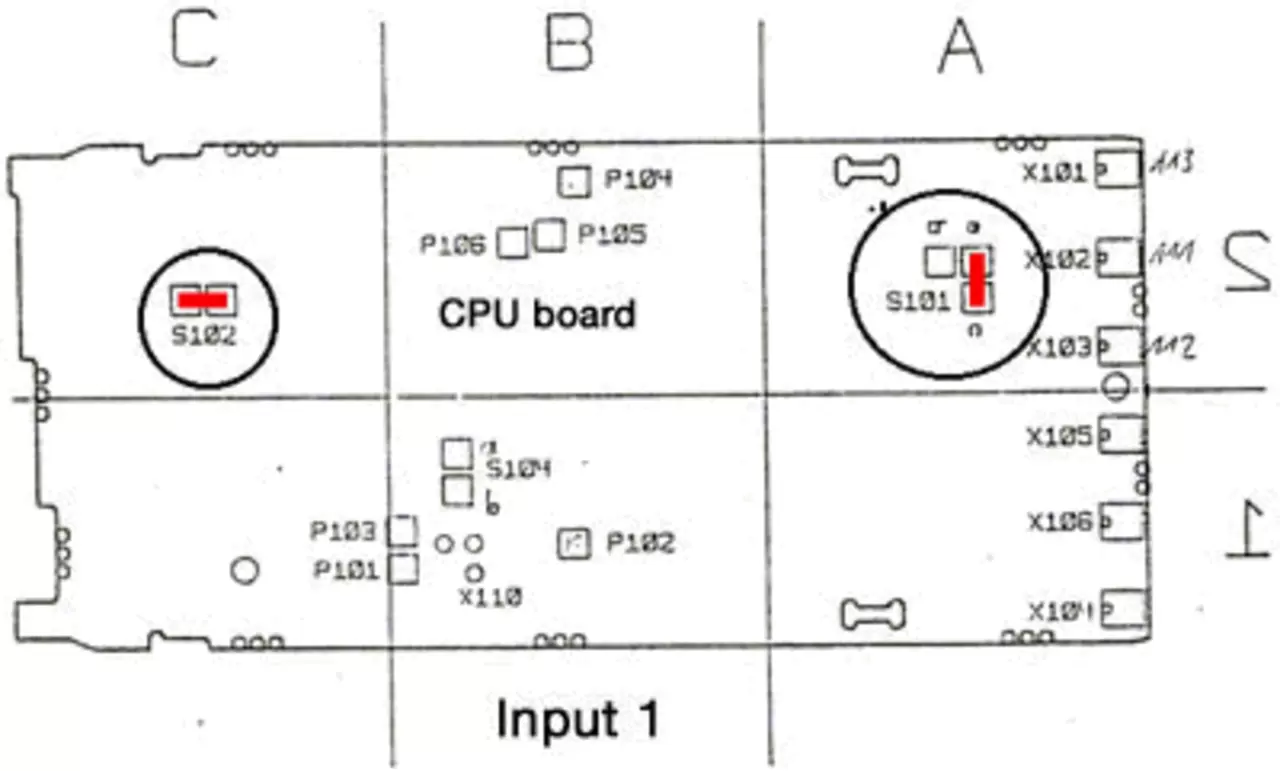
For standard universal input (RTD, thermocouple, current), solder bridges S101 and S102 on the CPU board are configured as follows:
If input 1 is to operate with 0...10 V (other signals are then no longer possible!), then the solder bridges on the CPU board must be modified as follows:
Bridge configuration for input signal 0...10V at input 1:
Cause: The configuration level was not called via parameter y.0
A PC setup program for configuring the controller from a PC is available for dTRON 16.1. Just like the PC program, JUMO Part No. 70/00400027, you will need an interface cable with a special adapter for dTRON 16.1.
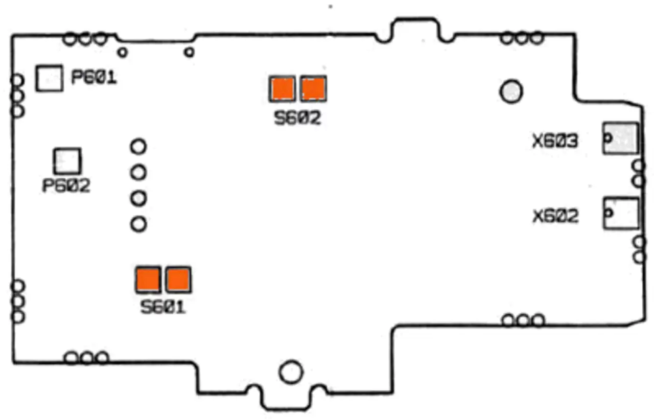
The analog output (output 3) is an optional output and is not installed in the standard device. If the output is enabled in order, the output signal can be changed between current and voltage by means of solder links on the output board. The 0 or 2 V, or 0 or 4 mA signal begins, and is set to configuration level C 114.
The type designation shows whether the dTRON 16.1 was supplied with an analogue output. Please refer to the operating instructions, chapter 2 "Identifying the device version".
The next two solders on the analog output board should be changed accordingly when changing between
Output range | Link S 602 (S1) | Link S 602 (S2) |
|---|---|---|
0/4 - 20 mA | open | open |
0/2 - 10 V | closed | closed |
Depending on the selected controller type, the following parameters are determined through autotuning:
Controller type | Parameter |
|---|---|
2-state controller ON/OFF | Pb1, dt, rt, Cy1, df |
3-state controller | Pb1, Pb2, dt, rt, Cy1, Cy2, df |
Proportional controller | Pb1, dt, rt, df |