Highly scalable paperless recorder
Find out more about the benefits and related technical specifications of JUMO LOGOSCREEN 700
Productinfos
Find out more about the benefits and related technical specifications of JUMO LOGOSCREEN 700
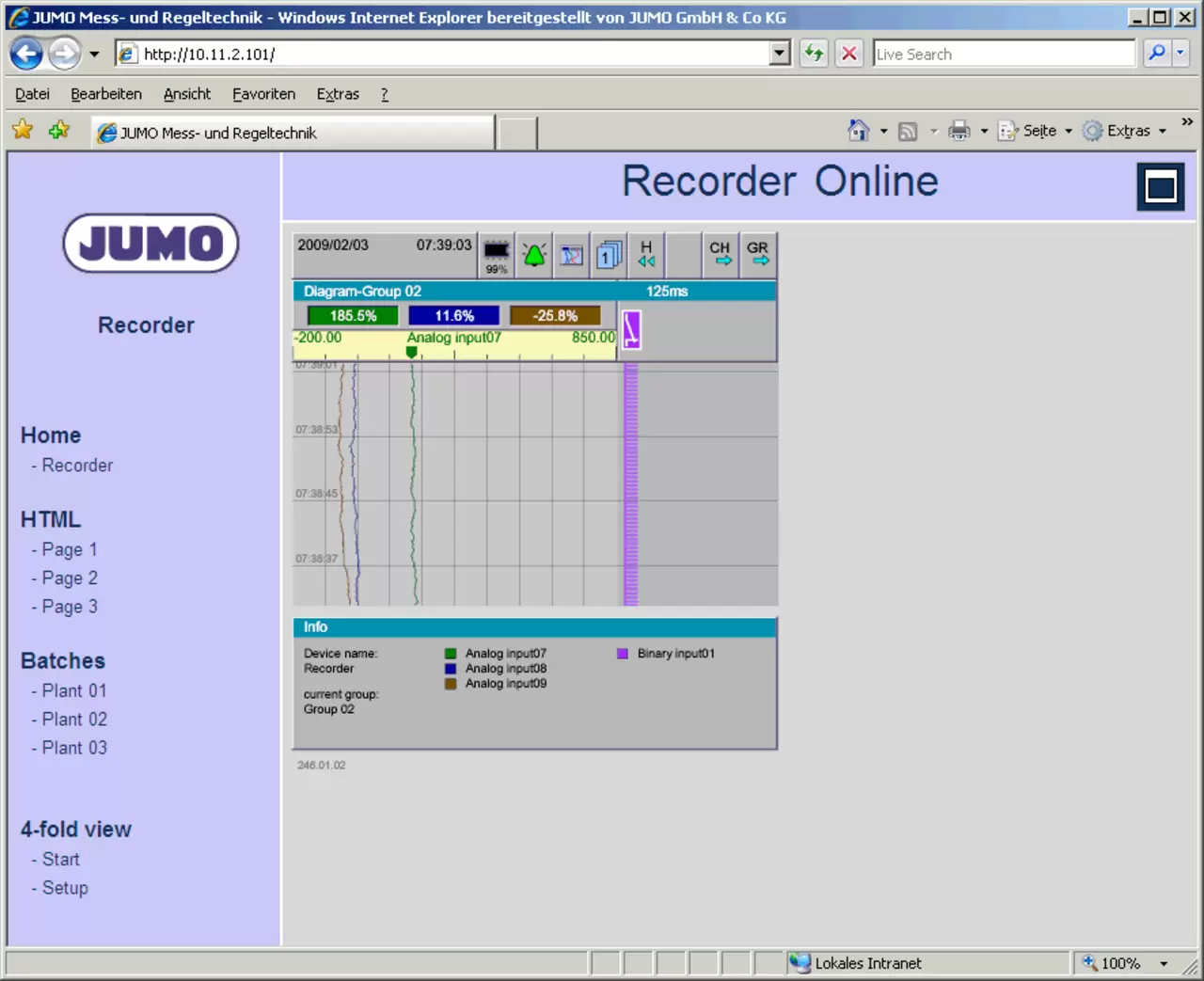
ProductinfosThe standard web server function JUMO LOGOSCREEN nt 706581 allows you to display the logger screen online to visualize the measurement data.
You can select and change the view on the PC regardless of the current display on the paperless recorder.
For security reasons, configuration changes can only be made through the setup program or directly on the recorder.
A brief introduction to web servers using JUMO LOGOSCREEN nt and a PC on a corporate network as examples:
1) Microsoft Internet Explorer is required as a web browser.
2) To display the SVG (Scalable Vector Graphics) images that are used on the web server, the correct web browser needs a plugin such as SVG Viewer from Adobe.http://www.adobe.com/svg)
3) Establishing a direct Ethernet connection between the PC and JUMO LOGOSCREEN nt, as described in the previous article.
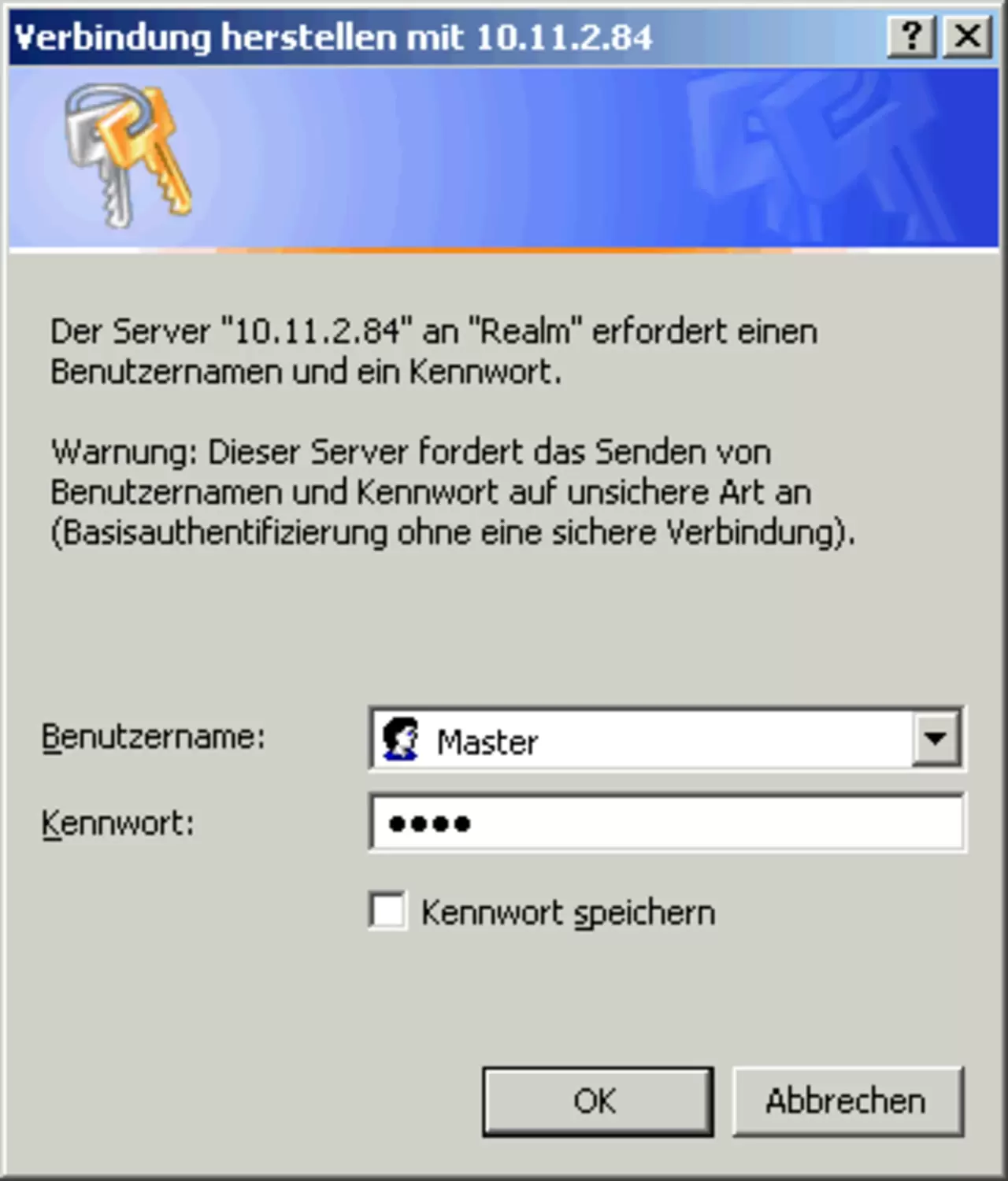
4) If the current IP address JUMO LOGOSREEN nt is entered into Internet Explorer, a window opens asking for the username and password to log in to JUMO LOGOSCREEN nt.
(Factory Setting: User=Master, Password=9200)
Then online visualization is installed. Here you can switch between different views.
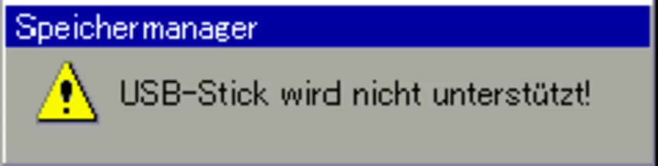
After the USB drive is inserted into the recorder, the following message appears:
The goal in Eco mode is to keep the number of stored measured values as low as possible while still clearly displaying the signal path.
The number of stored measured values depends on the dynamics of the measuring signal.
If the measurement signal is very stable, the measured values are only stored at relatively long intervals, which is determined by the "Min. Storage cycle" in the standard operation of the group configuration.
If a measured value deviates from a defined “tolerance band” for longer than the set “storage cycle”, additional measured values are stored.
If the focus is less on the detailed signal path and more on monitoring limitations, the number of stored measured values can also be reduced by storing a "Min/Max Value" in combination with a longer memory cycle, thereby saving storage space and, if necessary, transfer time.
More information about Eco mode can be found in Operating Instructions B 70.6581.0 in chapter 2.8.2.
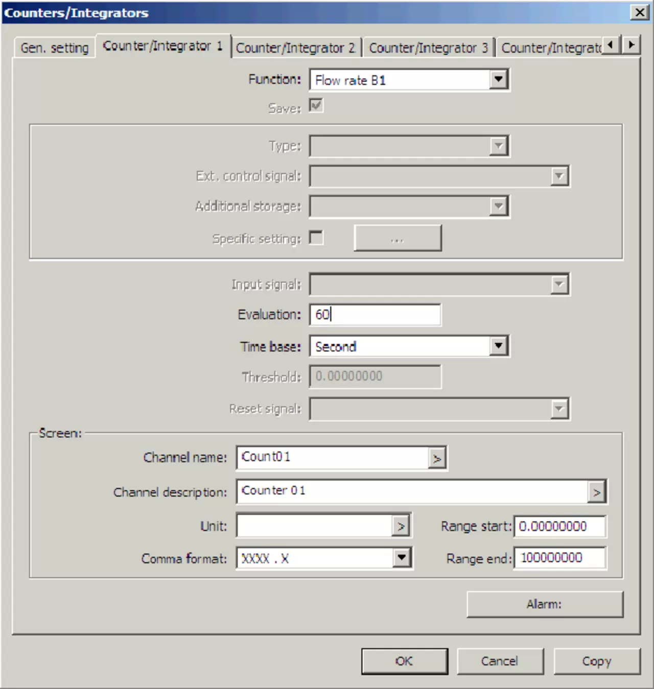
Information about the function "Number of revolutions B" on JUMO LOGOSCREEN nt
The "Number of Bx Threads" function is located in the "Counters/Integrators" menu.
Example:
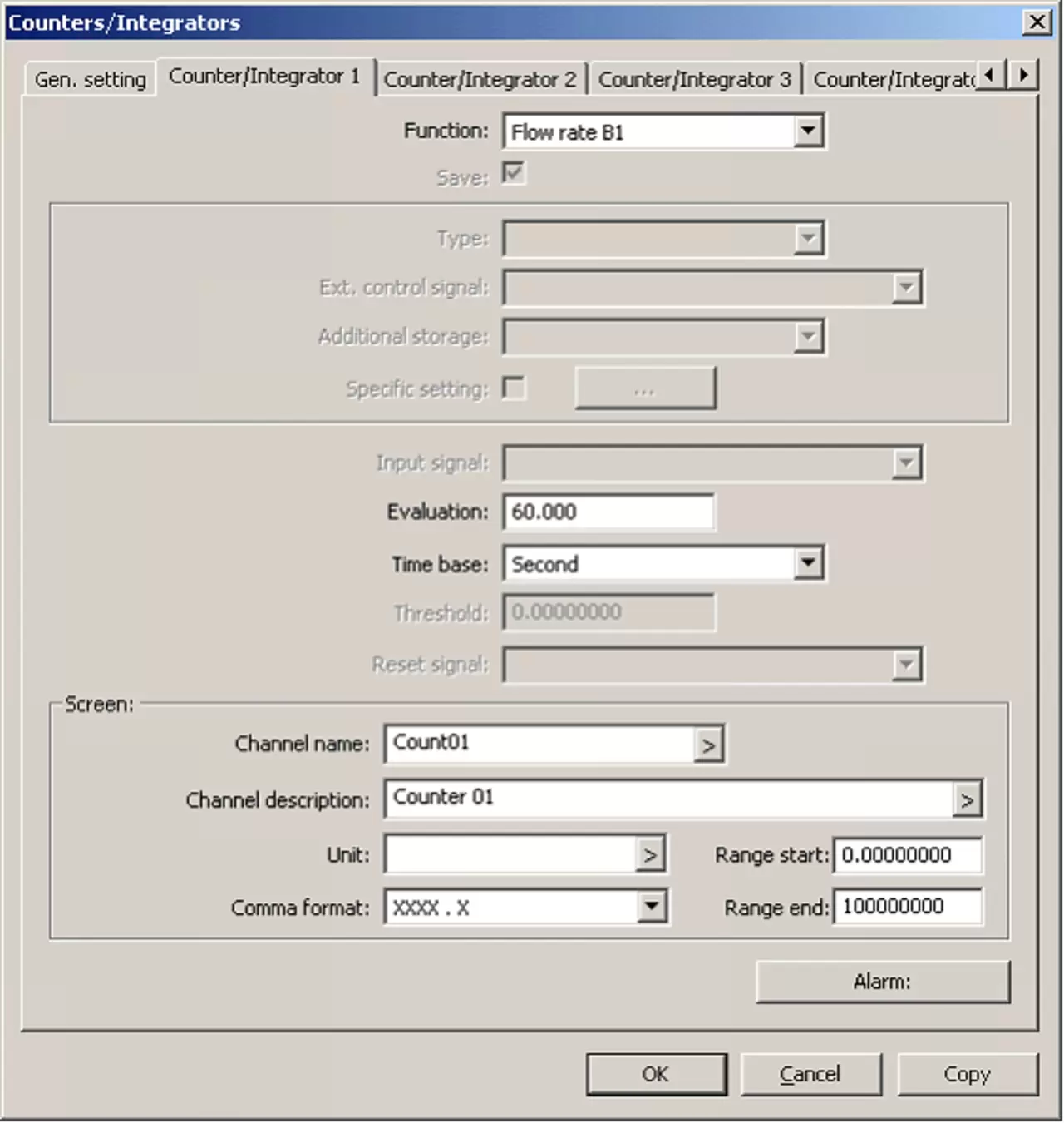
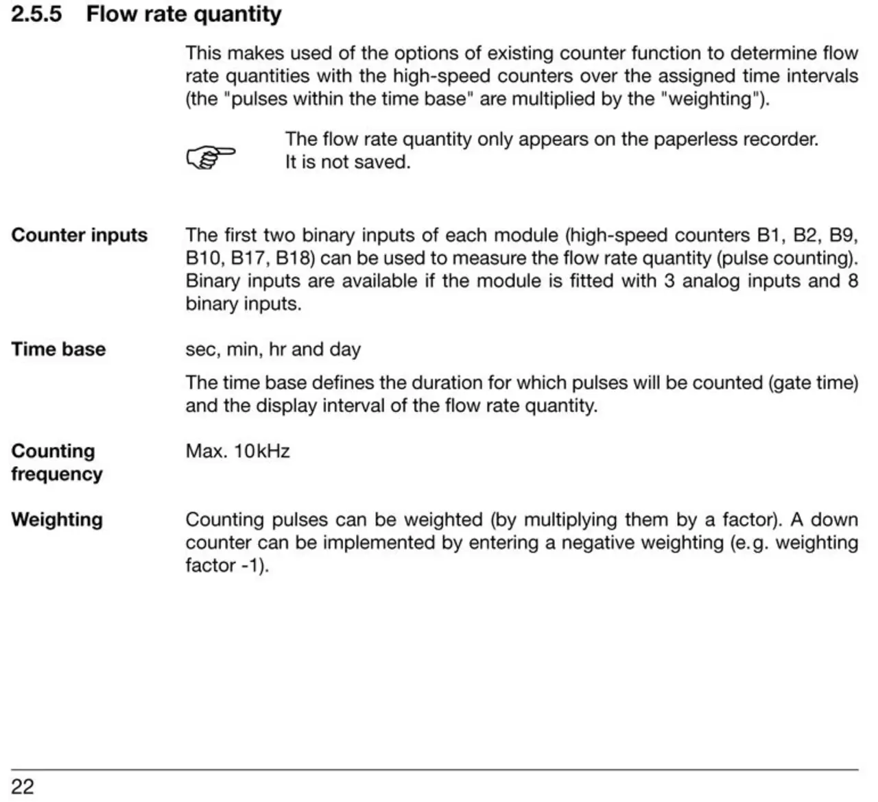
With one pulse per revolution, the speed in rpm can be displayed and stored as a string (= as an analogue signal) as follows:
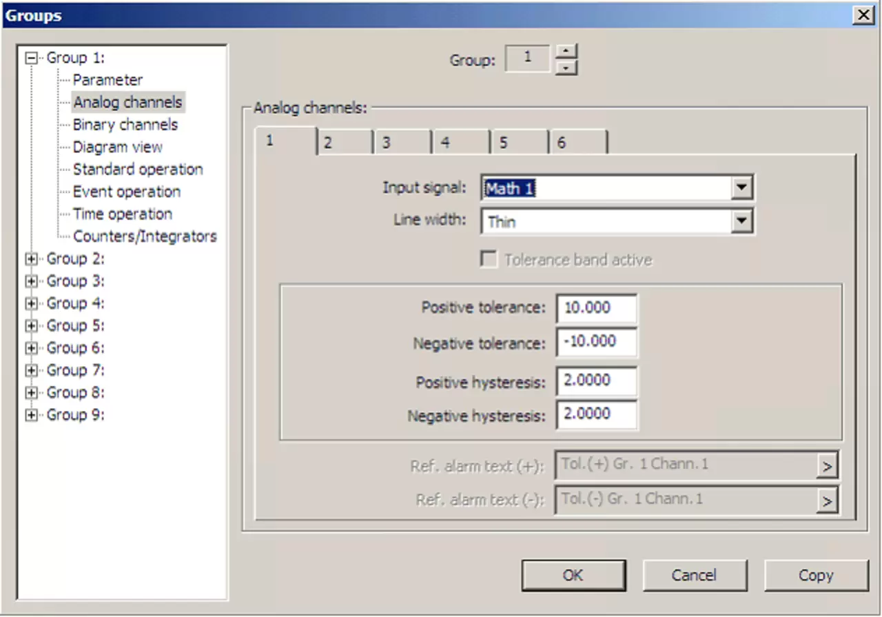
LOGOSCREEN NT
There are two possible options,
Communication module polling
Benefits:
Fast voting cycles
Disadvantage:
- Maximum 16 external inputs.
- Bindings must also be created in the iTOOL project.
Polling input modules
Benefits:
- Max. 24 external inputs are possible.
There is no need to create any additional bindings in the iTOOL project.
Disadvantage:
Slow polling cycles
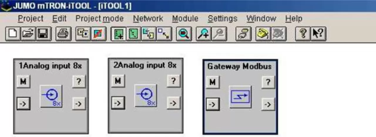
ITOOL_Project to poll the communication module
Using iTOOL, a project is created with a Modbus gateway and input modules.
In the example here, with 2 x 8-fold input modules.
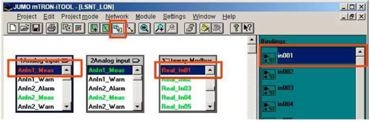
The second module corresponds to Real_In09 - Real_In16.
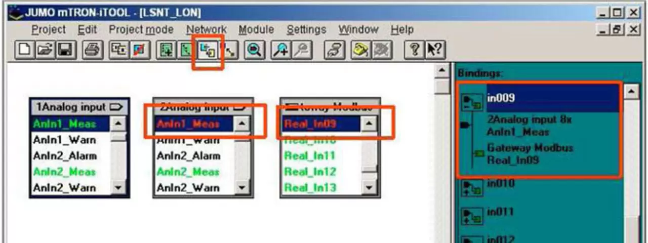
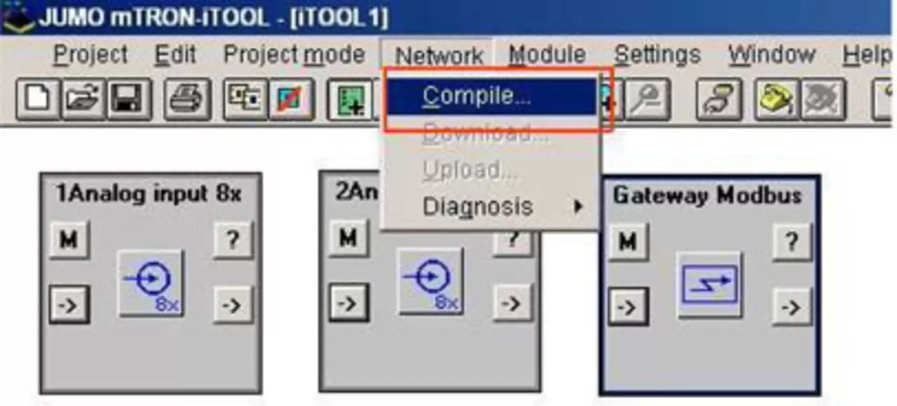
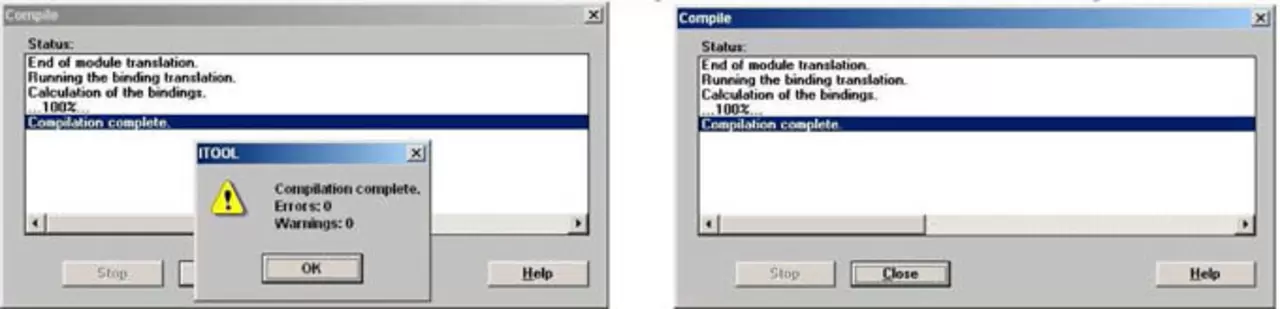
Confirm the note from iTOOL with OK and close the window with Close.
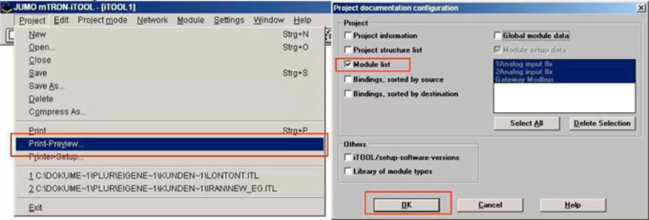
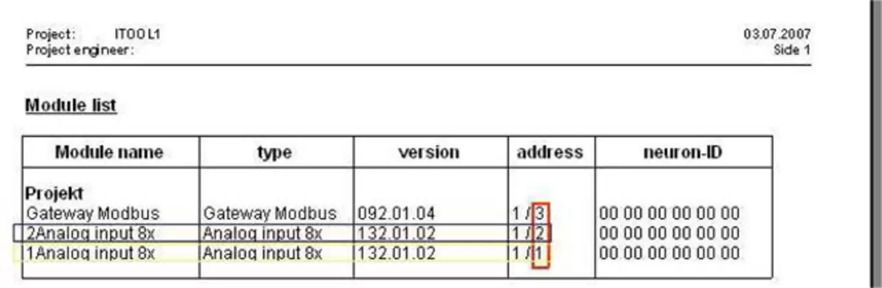
From the Project menu, select Print-Preview... and check the list of Modules. Open other options and confirm with OK.
Activating the Modbus Master Configuration in the Setup Program
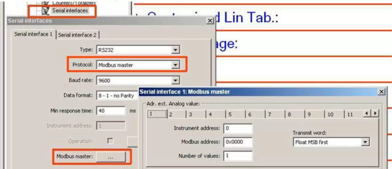
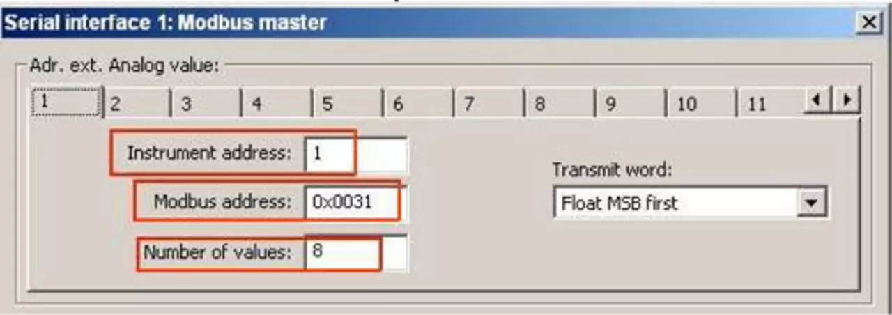
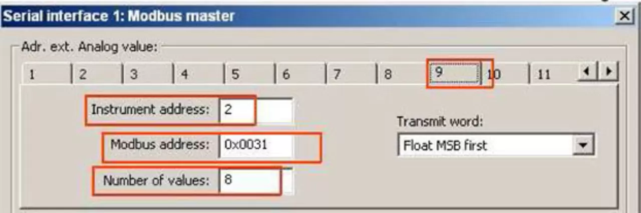
The slave address found in the Print Preview is now used as the tool address to enter the installer in the main Modbus configuration. The Modbus address can be found in the system manual (sh70.4040d.pdf).
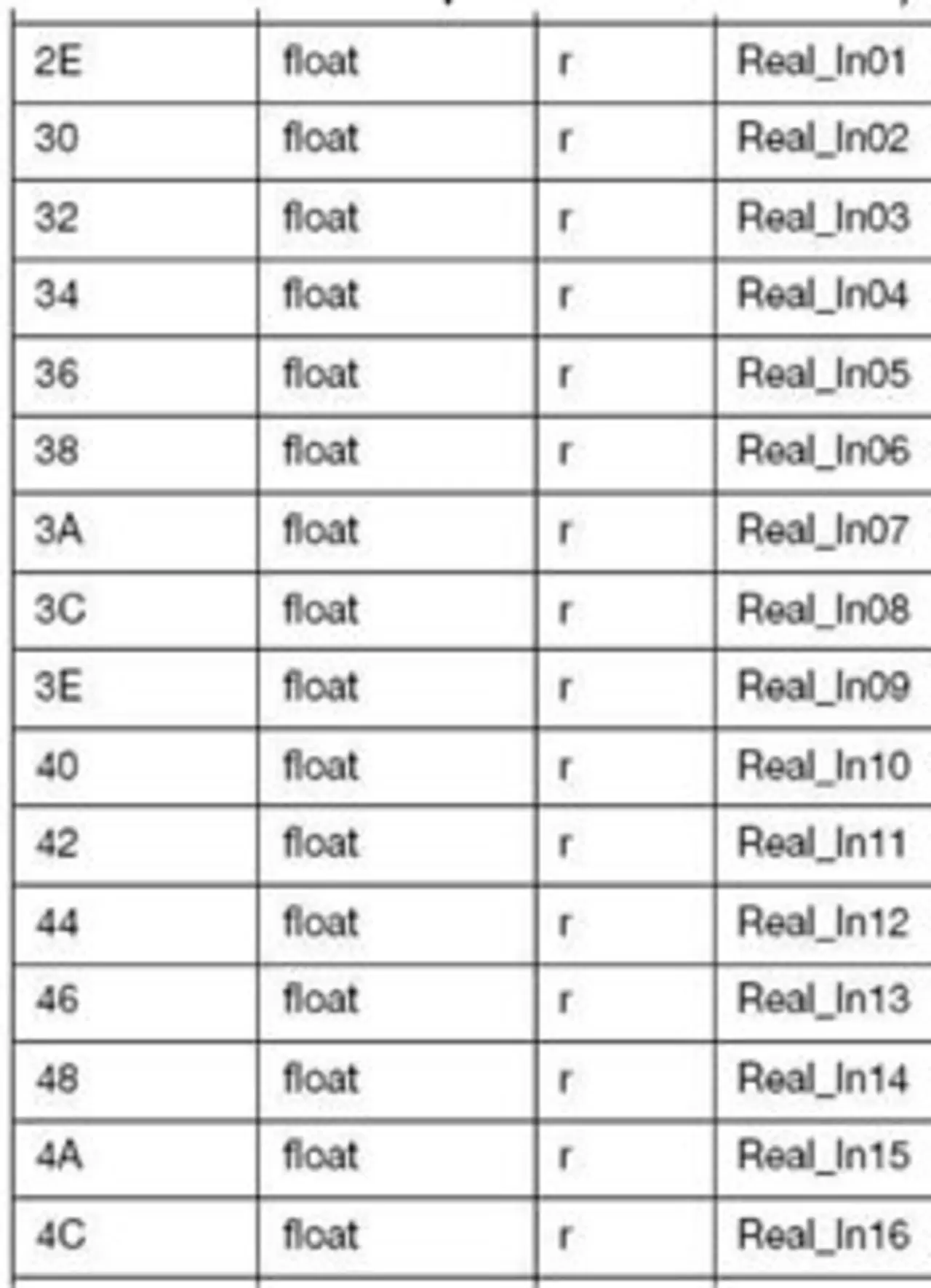
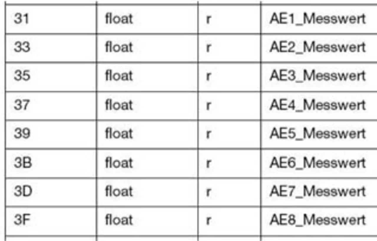
The following Modbus address table is used to interrogate the communication module.
(sh70.4040d.pdf page 51)
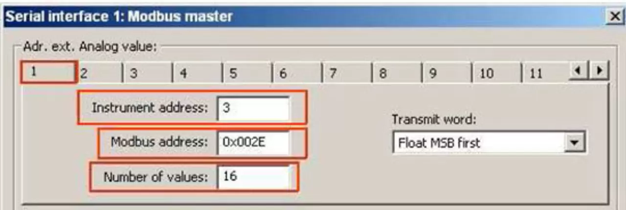
The number of values is the input option for polling serial ModBus addresses; With a communication module, it makes sense to enter 16 values here.
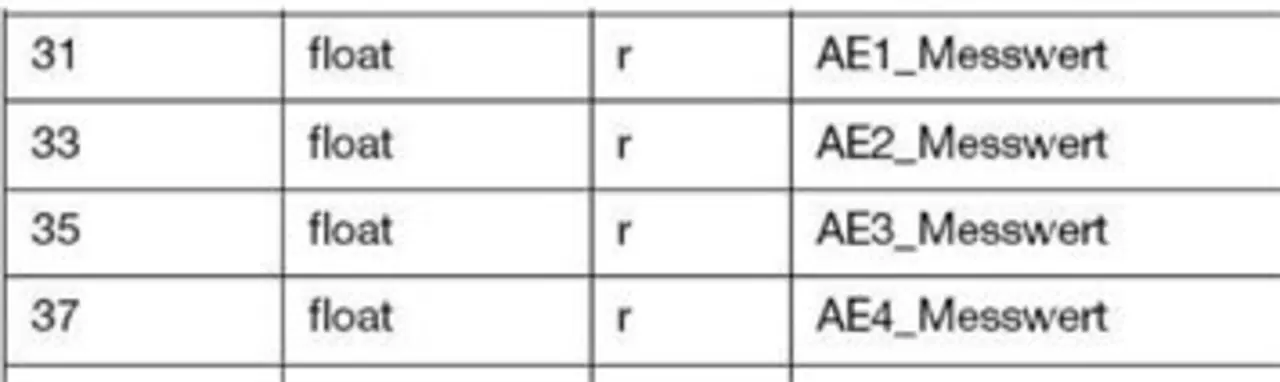
The number of values is the input option for polling serial ModBus addresses, in the example here the 8 values for the 4-fold module correspond to 4 values.
Plates 2 - 8 are inactive.
Explanation using the example of JUMO LOGOSCREEN nt and a PC or laptop with Windows XP:
The example is based on the factory default settings for the Ethernet interface.
The following screenshots show the Ethernet interface settings on JUMO LOGOSCREEN nt, which can be checked and changed if necessary.
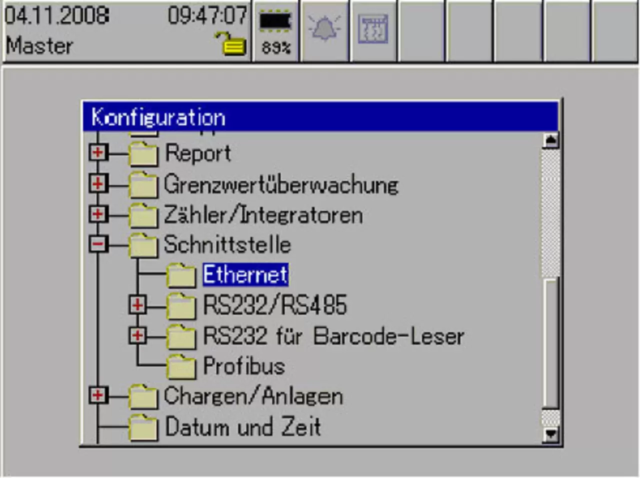
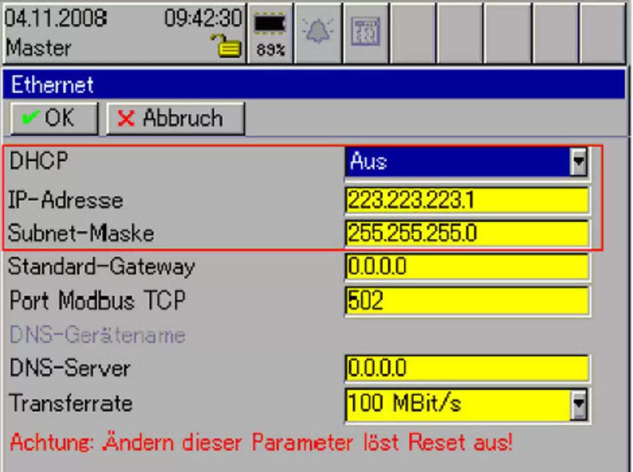
DHCP must be switched off. IP-address and subnet mask of JUMO LOGOSCREEN nt and PC must be coordinated. The following settings must be changed on the PC or laptop for direct connection via Ethernet:
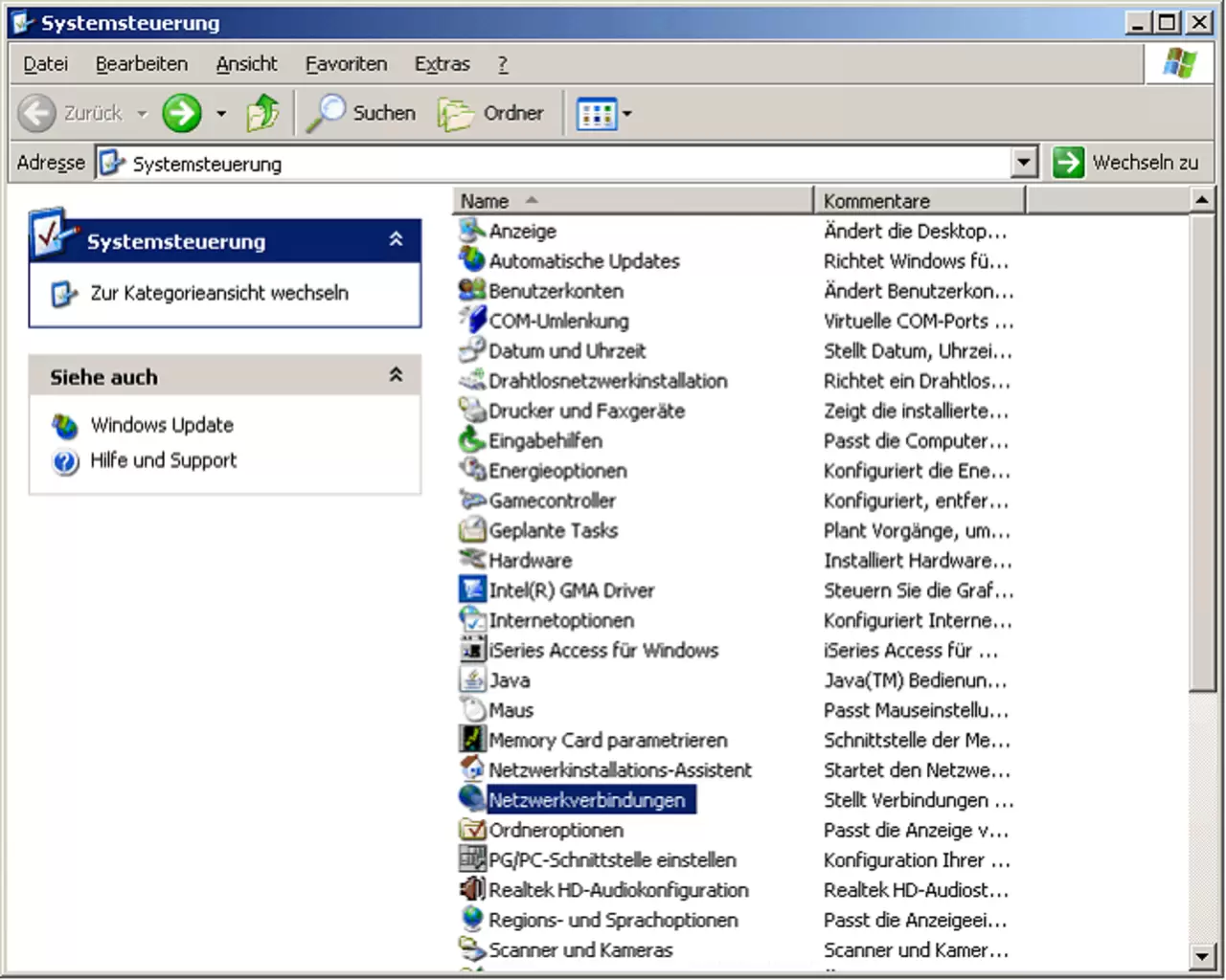
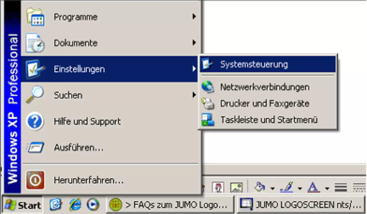
The right mouse button on the LAN connection opens the displayed Properties menu.
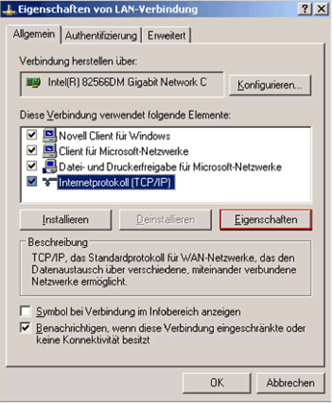
In the Properties section you will usually find the following default setting:
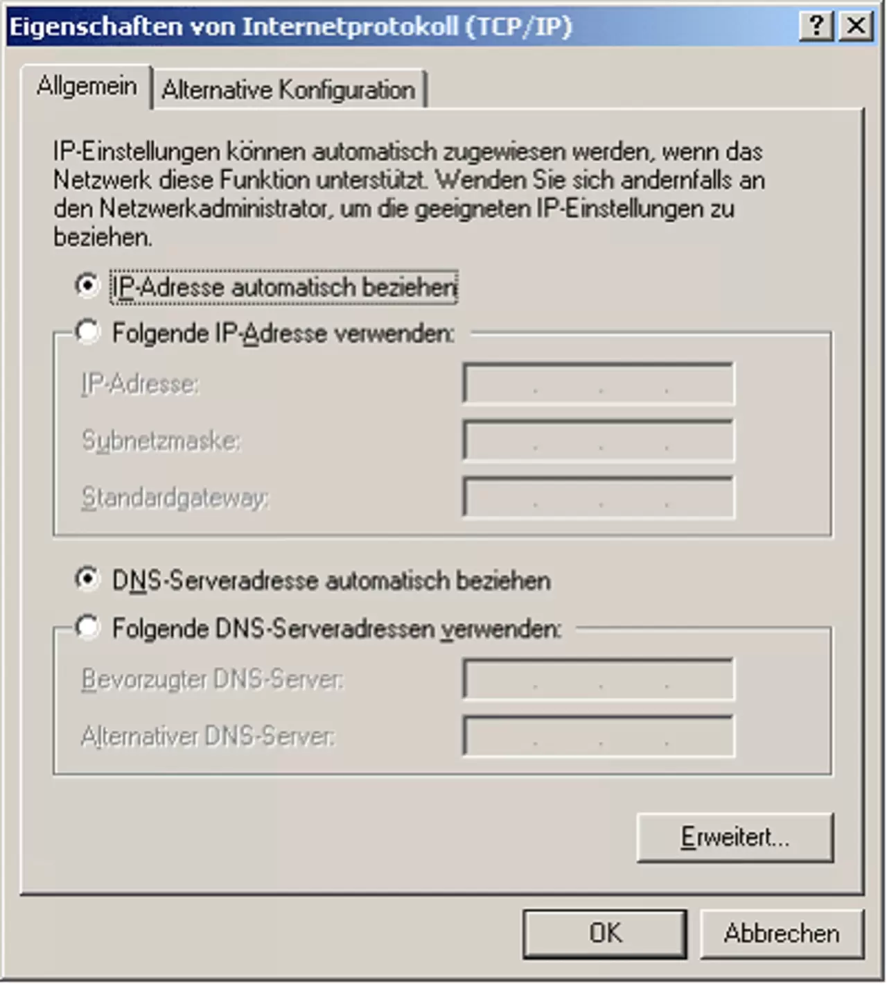
The following settings must be changed for a direct connection between the PC and JUMO LOGOSCREEN:
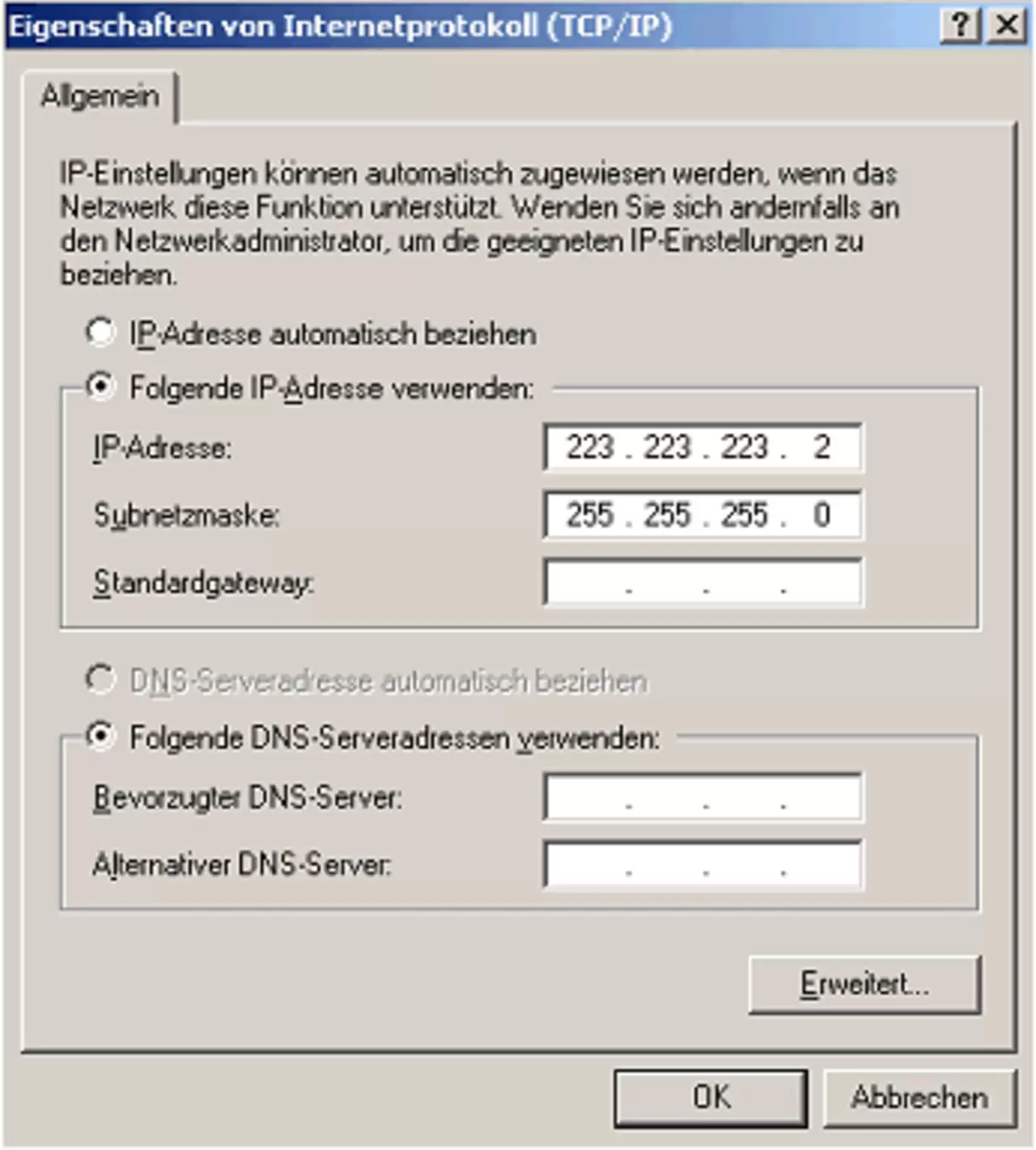
Connection and wiring:
A crossover cable (= patch cable with crossed connections) or a regular patch cable + crossover adapter with RJ45 connector is usually required for a direct Ethernet connection between a PC and JUMO LOGOSCREEN nt.
Newer laptops are more often able to adapt to a direct connection without a crossover, but with crossovers the cables are always on the safe side.
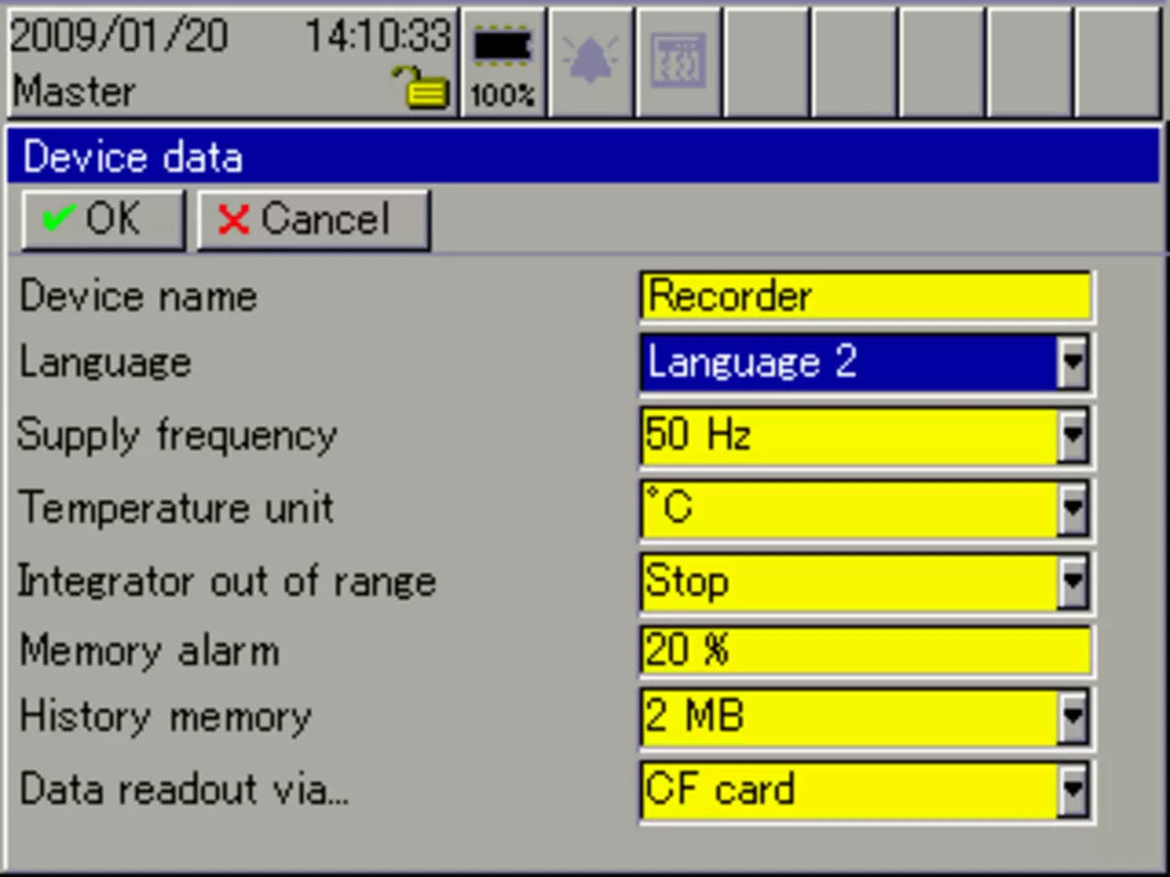
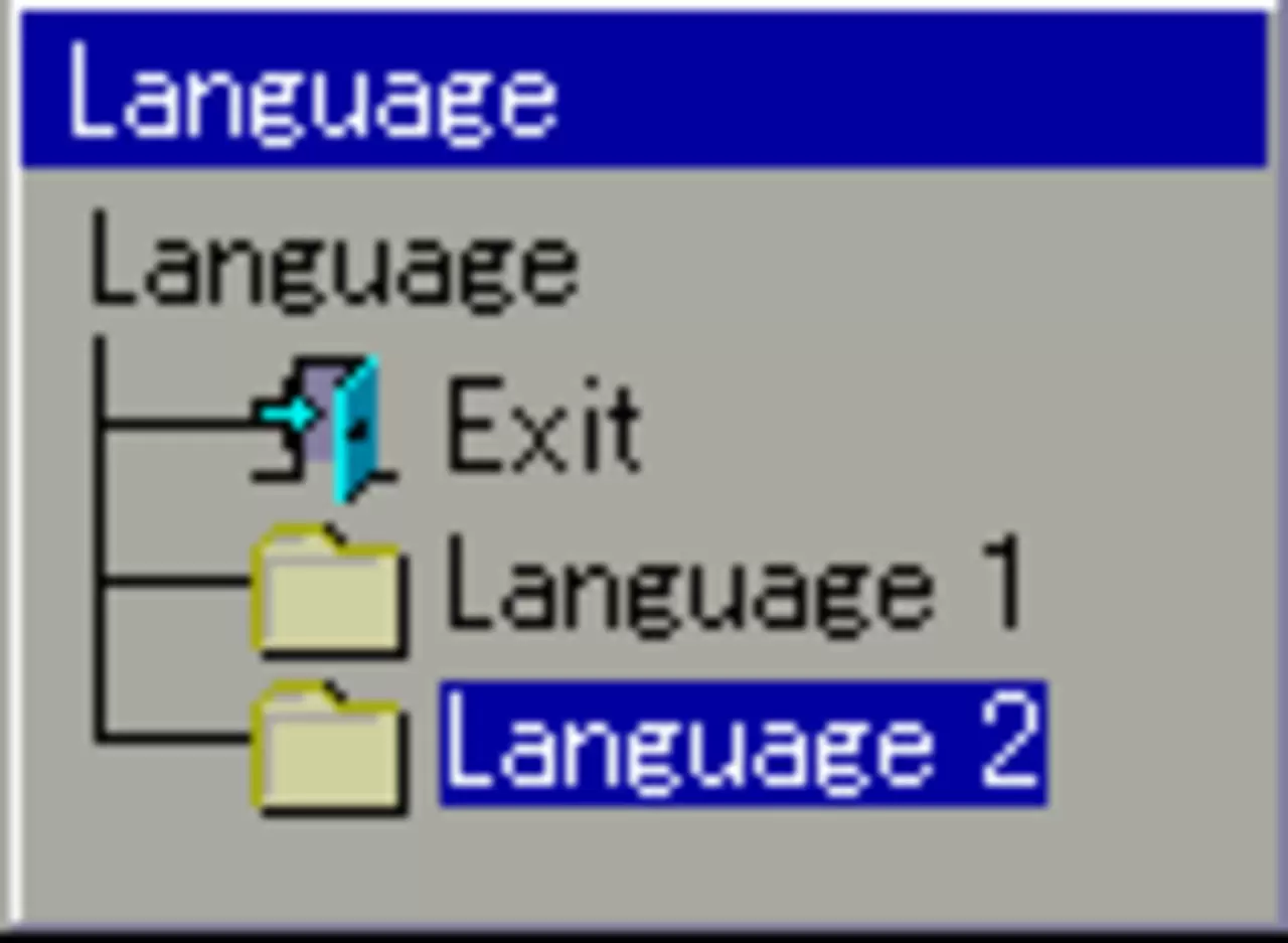
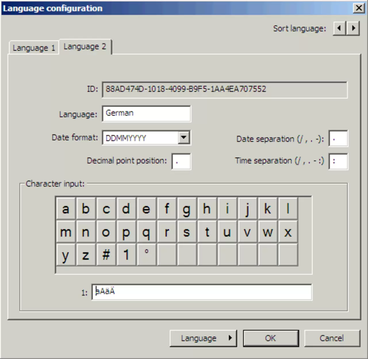
JUMO LOGOSCREEN nt stores 2 device language (default is GERMAN and ENGLISH). You can switch between these 2 languages on your device.

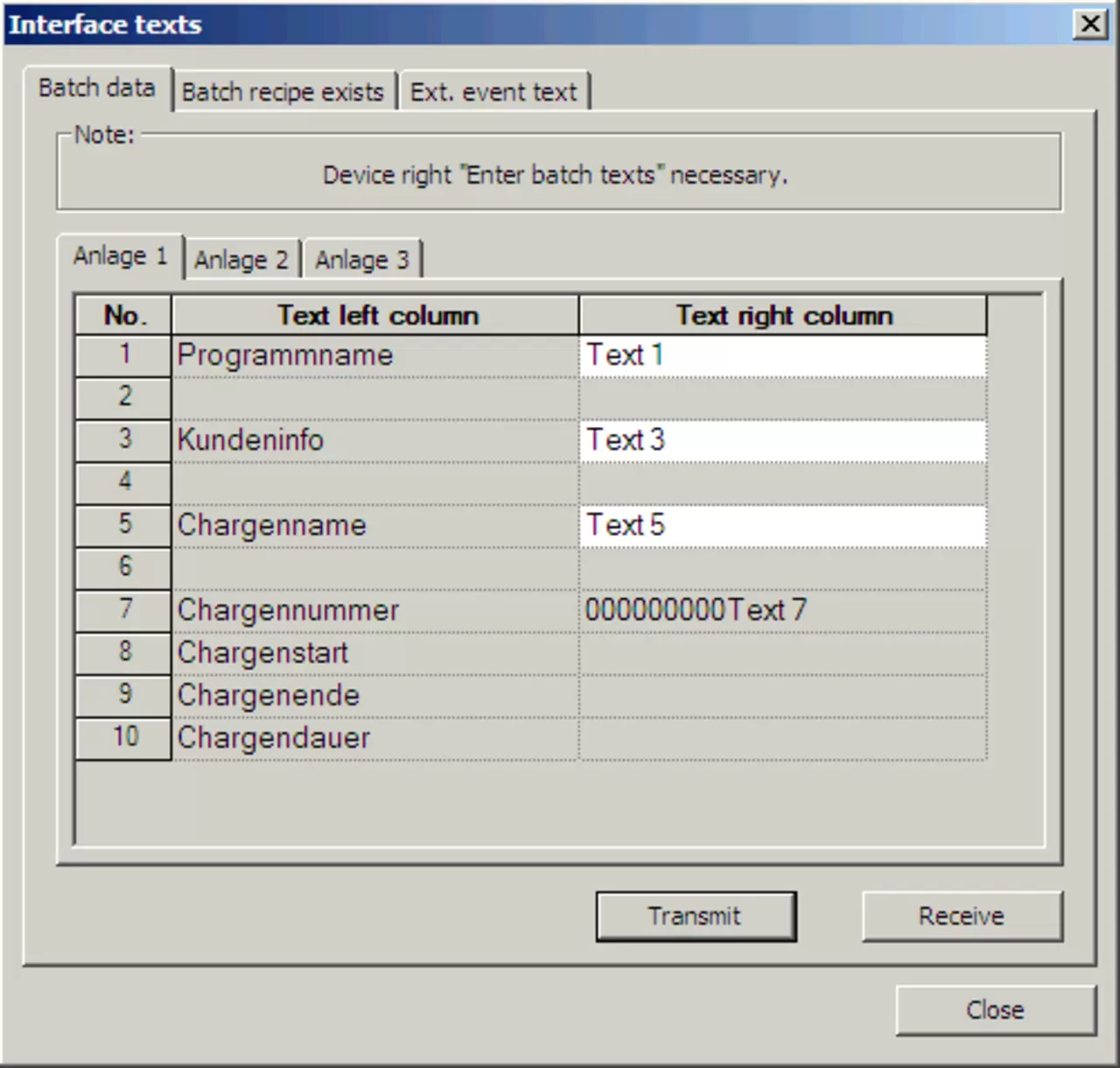
Batch texts can be entered and edited via the online setup program.
Enter batch texts for the current batch through the setup program using the PC keyboard.
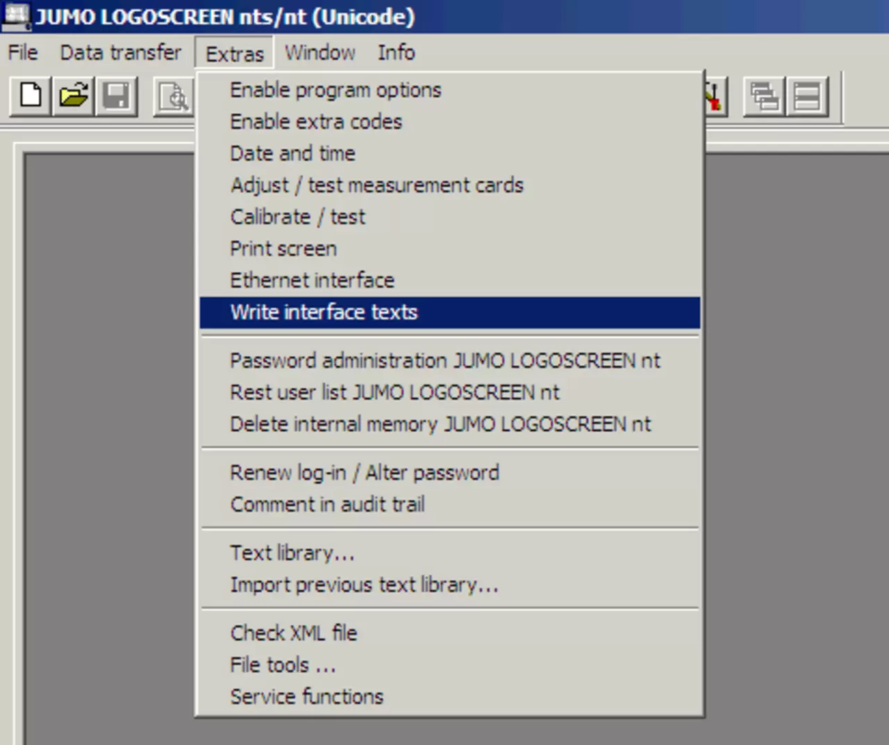
Online - Connect to JUMO LOGOSCREEN nt and select Write Interface Text from the Tools menu.
Edit batch text on PC and send to JUMO LOGOSCREEN nt
Why does the measured value view on screen JUMO LOGOSCREEN not disappear after changing to another view?
View in the evaluation program PCA3000:
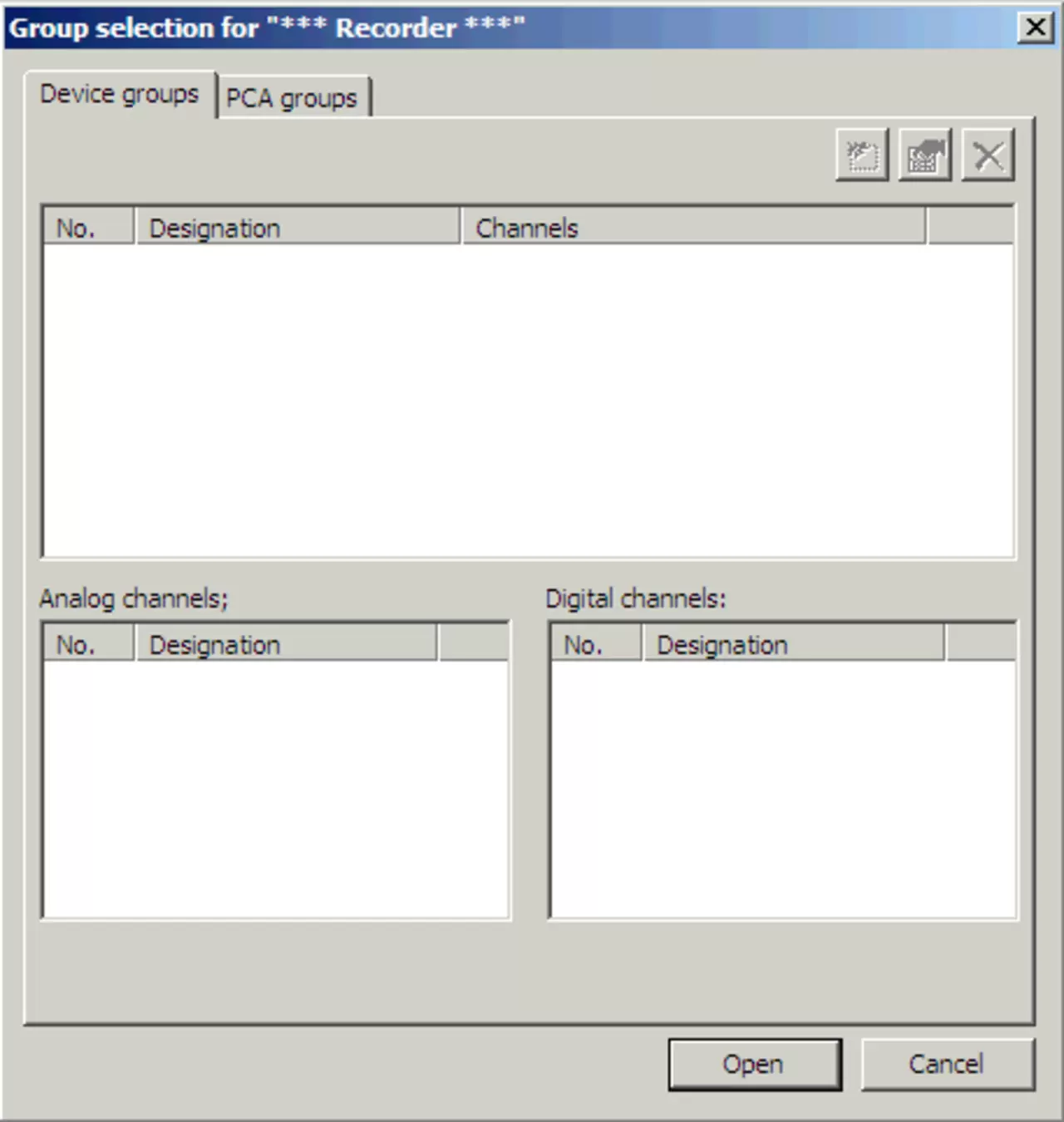
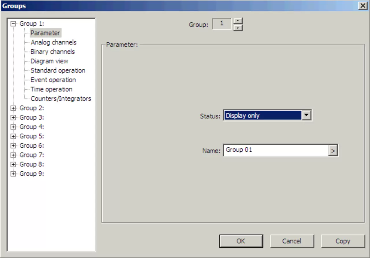
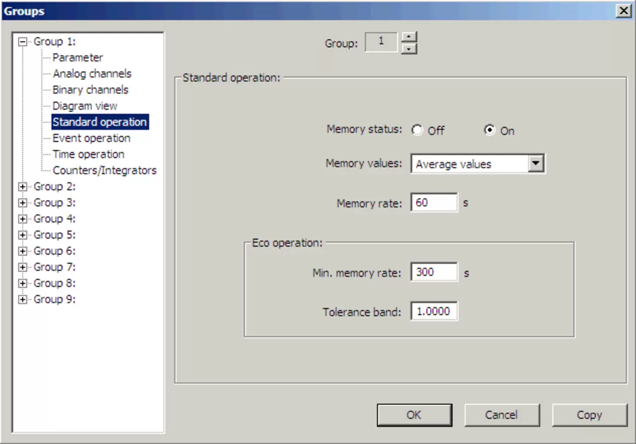
The time between 2 grid lines is the result of the current memory cycle multiplied by 60.
Examples:
Given a memory cycle of 0 seconds, JUMO LOGOSCCREEN operates with 125 milliseconds. This results in 7,5 seconds per grid.
In a memory cycle, 10 seconds 10 minutes lie between 2 grid lines. Approximately 24 minutes are displayed on the screen.
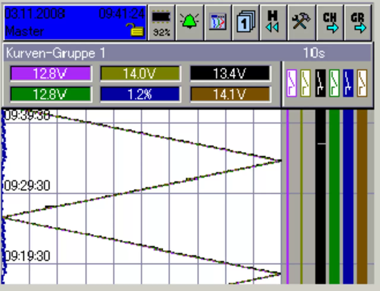
A display range independent of the actual memory cycle can be achieved as follows:
Settings are possible in the ONLINE dialog or via the CF card and are only accessible via the "Tools" menu item as follows with the setting program:
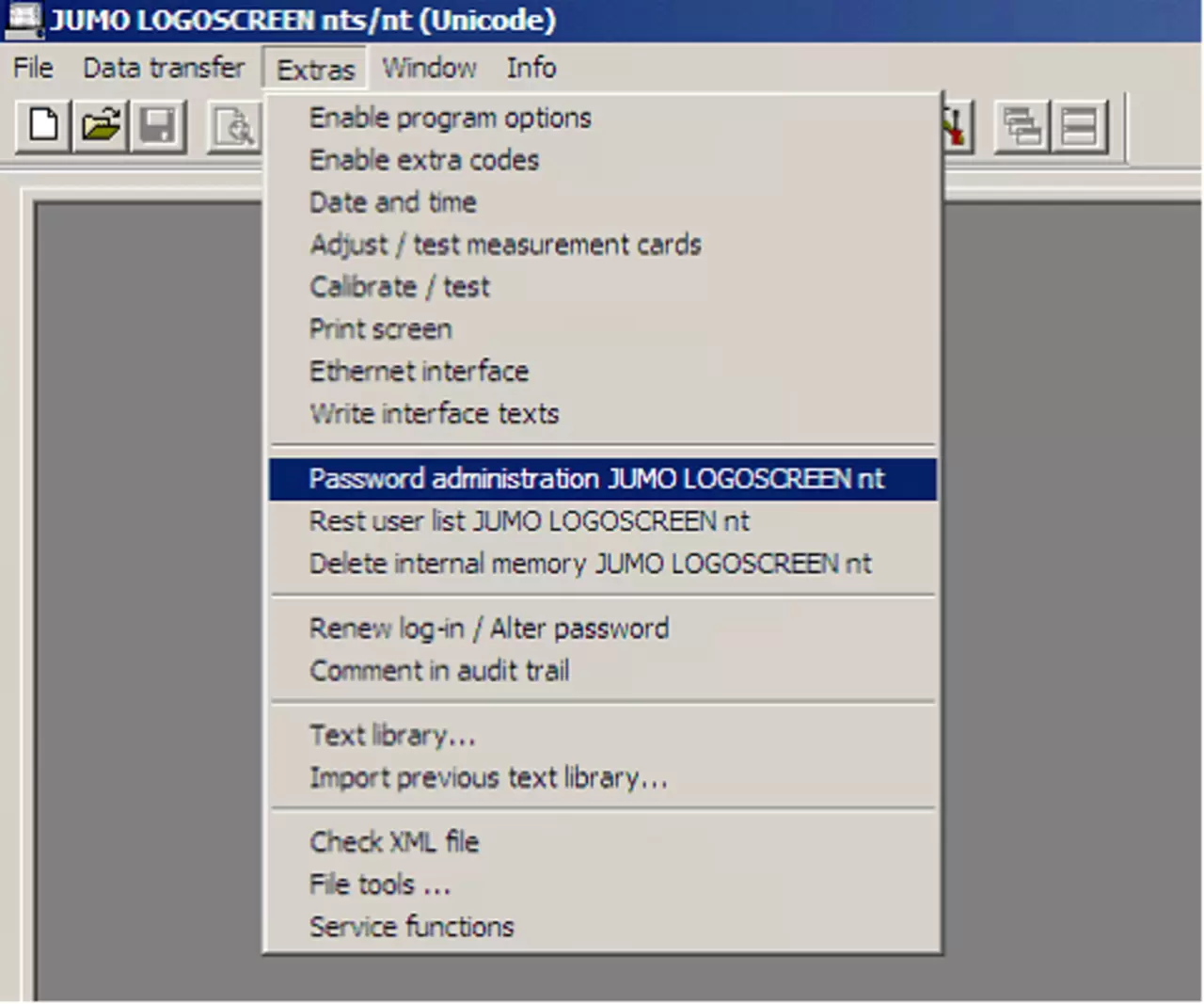
Selection for data transfer:
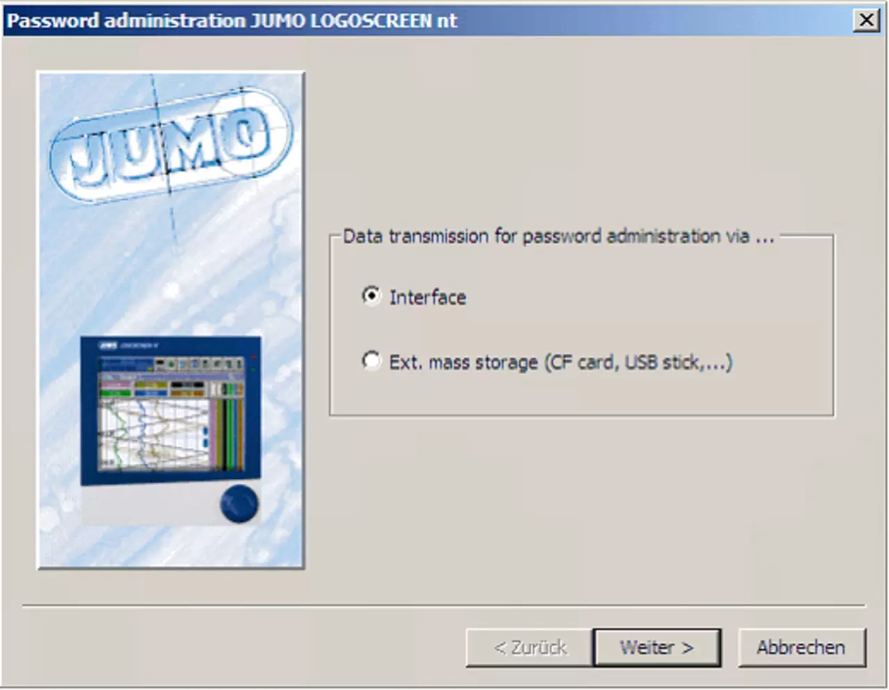
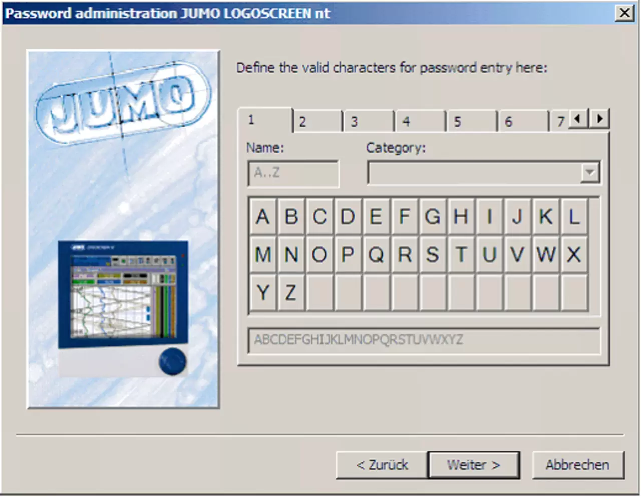
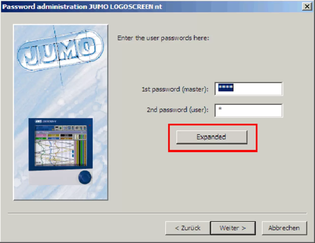
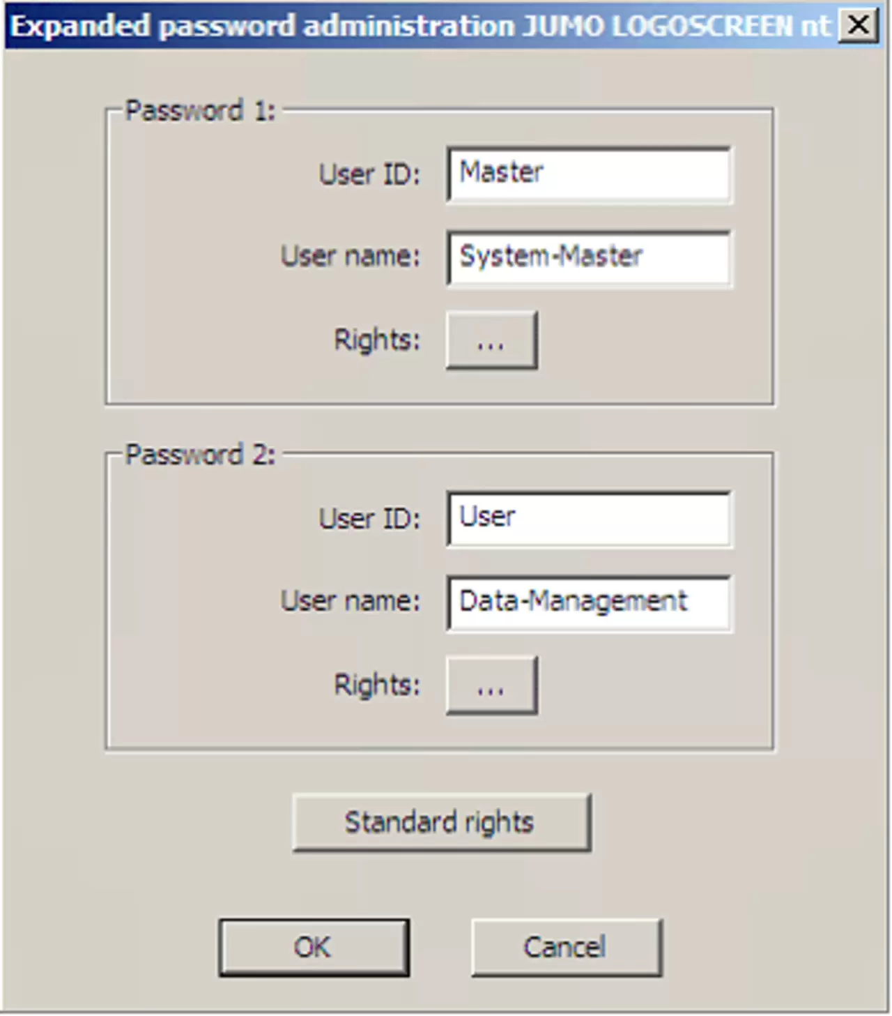
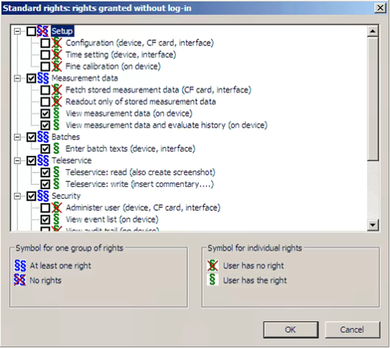
Default permissions setting: